Dell XPS 400 Owner's Manual - Page 75
If you insert the module correctly, the securing clips snap into the cutouts at each end of
 |
View all Dell XPS 400 manuals
Add to My Manuals
Save this manual to your list of manuals |
Page 75 highlights
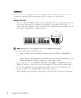
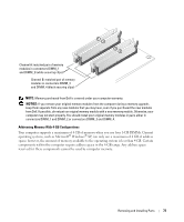
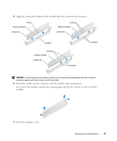
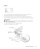
5 Align the notch on the bottom of the module with the crossbar in the connector. notch memory module cutouts (2) notches memory module cutouts (2) crossbar notches memory module cutouts (2) crossbars crossbars NOTICE: To avoid damage to the memory module, press the module straight down into the connector while you apply equal force to each end of the module. 6 Insert the module into the connector until the module snaps into position. If you insert the module correctly, the securing clips snap into the cutouts at each end of the module. 7 Close the computer cover. Removing and Installing Parts 75
-
 1
1 -
2
-
3
-
4
-
5
-
6
-
7
-
8
-
9
-
10
-
11
-
12
-
13
-
14
-
15
-
16
-
17
-
18
-
19
-
20
-
21
-
22
-
23
-
24
-
25
-
26
-
27
-
28
-
29
-
30
-
31
-
32
-
33
-
34
-
35
-
36
-
37
-
38
-
39
-
40
-
41
-
42
-
43
-
44
-
45
-
46
-
47
-
48
-
49
-
50
-
51
-
52
-
53
-
54
-
55
-
56
-
57
-
58
-
59
-
60
-
61
-
62
-
63
-
64
-
65
-
66
-
67
-
68
-
69
-
 70
70 -
 71
71 -
 72
72 -
 73
73 -
 74
74 -
 75
75 -
 76
76 -
 77
77 -
 78
78 -
 79
79 -
 80
80 -
81
-
82
-
83
-
84
-
85
-
86
-
87
-
88
-
89
-
90
-
91
-
92
-
93
-
94
-
95
-
96
-
97
-
98
-
99
-
100
-
101
-
102
-
103
-
104
-
105
-
106
-
107
-
108
-
109
-
110
-
111
-
112
-
113
-
114
-
115
-
116
-
117
-
118
-
119
-
120
-
121
-
122
-
123
-
124
-
125
-
126
-
127
-
128
-
129
-
130
-
131
-
132
-
133
-
134
-
135
-
136
-
137
-
138
-
139
-
140
-
141
-
142
-
143
-
144
-
145
-
146
-
147
-
148
 |
 |

Removing and Installing Parts
75
5
Align the notch on the bottom of the module with the crossbar in the connector.
NOTICE:
To avoid damage to the memory module, press the module straight down into the connector
while you apply equal force to each end of the module.
6
Insert the module into the connector until the module snaps into position.
If you insert the module correctly, the securing clips snap into the cutouts at each end of the
module.
7
Close the computer cover.
notches
memory module
cutouts (2)
crossbars
notch
memory module
cutouts (2)
crossbar
notches
memory module
cutouts (2)
crossbars