Esoteric G-02X Owners Manual EN FR SP - Page 7
Names and functions of parts, Frequency selection A/B buttons
 |
View all Esoteric G-02X manuals
Add to My Manuals
Save this manual to your list of manuals |
Page 7 highlights
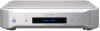
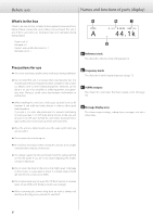
Names and functions of parts English ABC D E FG A POWER button Press this to turn the unit on and off. When the unit is on, the power indicator (ring around this button) lights blue. oo When the power is turned on, the unit starts warming the crystal oscillator (OCXO) up to its operating temperature. It takes two minutes for the oscillator frequency to stabilize. VVWhen you do not plan to use the unit for an extended amount of time, turn the preheat (PrHEAT) setting OFF and press the POWER button to turn the unit off. B LOCK indicator This shows the clock status. This blinks when locking or preheating or when an error occurs. It stays lit when locked completely. The indicator color changes according to the operation mode (MODE). It lights green when in Adaptive Zero Ground (A.GND) mode and lights blue when in normal (NORM) mode. C MENU button Press to enter setting mode (page 14). When in setting mode, this changes the setting item. D Remote control signal receiver This receives signals from the remote control. When using the remote control, point the end of it toward this receiver panel. oo This unit does not include a remote control. oo The dimmer of this unit can be adjusted using a remote con- trol included with other Esoteric products (page 15). E Display This shows the output clock frequency (ordinary display), setting screens and error messages. oo During ordinary display, if any output is on, the name and output frequency of the one that was last set is shown. oo "A", "B" or "10MHz" will usually appear. "NO OUTPUT" will appear if none of these are being output. F Frequency selection (A/B) buttons Use these to set the clock frequency output from the CLOCK OUT connectors (page 11). When in setting mode, press to select a setting item (page 14). G 10MHz button Press this to turn the 10MHz OUT connector output on and off (page 10). Press when in setting mode to quit setting mode. oo Use the menu to set which 10MHz OUT connectors (1-4) to use (page 16). 7
-
 1
1 -
 2
2 -
 3
3 -
 4
4 -
 5
5 -
 6
6 -
 7
7 -
 8
8 -
 9
9 -
 10
10 -
 11
11 -
 12
12 -
13
-
14
-
15
-
16
-
17
-
18
-
19
-
20
-
21
-
22
-
23
-
24
-
25
-
26
-
27
-
28
-
29
-
30
-
31
-
32
-
33
-
34
-
35
-
36
-
37
-
38
-
39
-
40
-
41
-
42
-
43
-
44
-
45
-
46
-
47
-
48
-
49
-
50
-
51
-
52
-
53
-
54
-
55
-
56
-
57
-
58
-
59
-
60
 |
 |
