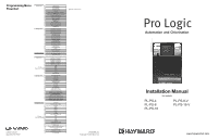
Hayward Pro Logic Models: PL-PS-4 PL-PS-8 PL-PS-16 PL-PS-16V Installation
Hayward Pro Logic Manual
 |
View all Hayward Pro Logic manuals
Add to My Manuals
Save this manual to your list of manuals |
Hayward Pro Logic manual content summary:
- Hayward Pro Logic | Models: PL-PS-4 PL-PS-8 PL-PS-16 PL-PS-16V Installation - Page 1
24 hour time format ºF or ºC vsp speed (% or rpm) reset colorlogic to default reset to default denotes conditional items 092330D RevG Copyright © 2010 Hayward Pro Logic Automation and Chlorination Installation Manual for models PL-PS-4 PL-PS-8 PL-PS-16 PL-PS-8-V PL-PS-16-V www.haywardnet.com - Hayward Pro Logic | Models: PL-PS-4 PL-PS-8 PL-PS-16 PL-PS-16V Installation - Page 2
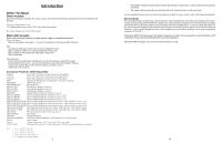
INSTRUCTIONS LIMITED WARRANTY (effective 04/01/09) Hayward/Goldline warrants its Pro Logic and E-Command pool automation products as well as its Aqua Rite, Aqua Rite Pro, Aqua Plus and SwimPure chlorination products to be free of defects in materials and workmanship, under normal use and service - Hayward Pro Logic | Models: PL-PS-4 PL-PS-8 PL-PS-16 PL-PS-16V Installation - Page 3
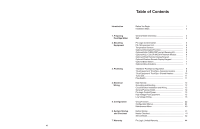
Spa - Shared Heaters 10 Turbo Cell 11 Flow Switch 11 4. Electrical Wiring Main Service 12 Grounding and Bonding 12 Circuit Breaker Installation and Wiring 12 General Purpose Outlet 12 Pro Logic Control Power 13 High Voltage Pool Equipment 13 Low Voltage Wiring 15 5. Configuration Group - Hayward Pro Logic | Models: PL-PS-4 PL-PS-8 PL-PS-16 PL-PS-16V Installation - Page 4
you may need to complete an installation include: Circuit breakers None are included with control-see page 12 and inside of door for suitable breakers Wire 4-conductor cable (electronics unit to remote display/keypad) Wire/conduit for 100A service from main panel to Pro Logic Wire/conduit for filter - Hayward Pro Logic | Models: PL-PS-4 PL-PS-8 PL-PS-16 PL-PS-16V Installation - Page 5
Turbo Cell Flow Switch 4. Electrical Wiring (page 12) Main service Grounding and bonding Circuit breakers Pro Logic control power High Voltage pool equipment Low voltage wiring (temperature sensors, flow switch, etc.) 5. Pro Logic control configuration (program desired control operation) (page - Hayward Pro Logic | Models: PL-PS-4 PL-PS-8 PL-PS-16 PL-PS-16V Installation - Page 6
pool, per manufacturer's instructions. This ensures a quick, troublefree transfer to the Pro Logic system. 3 if any output is configured as a variable speed pump VSP Speed % Toggle between % and RPM Move to previous/next configuration menu This is the unit of measure for displaying the speed of - Hayward Pro Logic | Models: PL-PS-4 PL-PS-8 PL-PS-16 PL-PS-16V Installation - Page 7
power up. Select which of the available remote controls (A, B or C) is to be configured. Digital A, Button 1 This menu allows the user to map each button of the AQL-SS-D to one of the standard Pro Logic functions. The default selections are: Button 1 - Pool/Spa, Button 2 - Filter, Button 3 - Lights - Hayward Pro Logic | Models: PL-PS-4 PL-PS-8 PL-PS-16 PL-PS-16V Installation - Page 8
selected freeze protection temperature, the Pro Logic will turn on the valve to allow circulation of the water. IMPORTANT: this only enables operation of the valve3 output during freeze--see the "Filter Pump Config." menu to enable freeze protection for the main circulation system. Freeze protection - Hayward Pro Logic | Models: PL-PS-4 PL-PS-8 PL-PS-16 PL-PS-16V Installation - Page 9
AQL-COLOR-MODHV network module, the Pro Logic can fully control the color, speed, motion and brightness of Hayward ColorLogic Generation 4 pool and spa lights as well as provide programmable light shows. Refer to the AQL-COLOR-MODHV for detailed installation, wiring and operation information. 6 - Hayward Pro Logic | Models: PL-PS-4 PL-PS-8 PL-PS-16 PL-PS-16V Installation - Page 10
the cable from the Pro Logic main unit to the remote control. Also refer to the remote's installation instructions for more information. AQL2-Wx-PS-x (x=4,8, or 16) The AQL2-Wx-PS-x is a wall mounted display/keypad which must be mounted indoors or in a weather protected area (rain should never - Hayward Pro Logic | Models: PL-PS-4 PL-PS-8 PL-PS-16 PL-PS-16V Installation - Page 11
system is in the "pool only" operating mode. 6. The plumbing diagram above is intended to be used as a general guideline and is not a complete plumbing schematic for the pool. 7. The air sensor must be installed if the freeze protection feature is enabled for the filter, valves or aux outputs - Hayward Pro Logic | Models: PL-PS-4 PL-PS-8 PL-PS-16 PL-PS-16V Installation - Page 12
Pro Logic can be programmed to accommodate spillover if desired. Note that spillover operation will be automatically suspended whenever the spa filter pump is turned on. 9 lights relay during freeze--see the "Filter Pump Config." menu to enable freeze protection for the main circulation system - Hayward Pro Logic | Models: PL-PS-4 PL-PS-8 PL-PS-16 PL-PS-16V Installation - Page 13
the lights relay against freeze damage. If Freeze Protection is enabled and the AIR temperature sensor falls below the selected freeze temperature threshold, the Pro Logic will energize the lights relay. IMPORTANT: this only enables operation of the 33 5. The chlorinator cell must be installed in - Hayward Pro Logic | Models: PL-PS-4 PL-PS-8 PL-PS-16 PL-PS-16V Installation - Page 14
To ensure proper operation, verify that the arrow on the flow switch points in the direction of water flow 11 NOTE: If an AQL-COLOR-MODHV ColorLogic Network Module is detected at startup, only the Lights Name menu will appear under Lights Configuration. Refer to the AQL-COLOR-MODHV manual for more - Hayward Pro Logic | Models: PL-PS-4 PL-PS-8 PL-PS-16 PL-PS-16V Installation - Page 15
) codes -Use copper conductors only Main Service (Power to the Circuit Breaker Subpanel) The Pro Logic circuit breaker subpanel is rated for 100A service. Run properly rated conductors (L1, L2, N, and ground) from the primary house electrical panel to the main power connections on the Pro Logic - Hayward Pro Logic | Models: PL-PS-4 PL-PS-8 PL-PS-16 PL-PS-16V Installation - Page 16
Pro Logic Control Power The Pro Logic requires 120VAC, 2A power to operate the control logic circuits and the chlorinator. This power should be connected to one of the circuit breakers. ! WARNING: 120VAC only (permanent damage if connected to 240V) Field Wired 120, 2VA Factory Prewired Neutral - Hayward Pro Logic | Models: PL-PS-4 PL-PS-8 PL-PS-16 PL-PS-16V Installation - Page 17
, low voltage communication wiring, and menu configuration/settings. The Pro Logic can control up to 2 Hayward TriStar VSPs and 8 EcoStar VSPs. Refer to the diagram below for proper input wiring to the VSP. Wiring from the 220V breaker must connect through the Pro Logic's Filter/Lights/Aux relay - Hayward Pro Logic | Models: PL-PS-4 PL-PS-8 PL-PS-16 PL-PS-16V Installation - Page 18
heaters, contact Hayward Tech support, 908-355-7995. Refer to the diagrams and the information on the following pages for more details on the connection to several popular heaters. Generic Heaters 1. Wire heater to 120/240V power source per the instructions in the heater manual. The Pro Logic - Hayward Pro Logic | Models: PL-PS-4 PL-PS-8 PL-PS-16 PL-PS-16V Installation - Page 19
white remove jumper white Fusible Link Hayward Heaters Refer to the instructions in the heater manual for "2-wire Remote Thermostat" operation under "Remote Control Connections" and the diagram on the below: 1. Turn off power to heater. 2. Wire Pro Logic to terminals 1 & 2 (see diagram). 3. Leave - Hayward Pro Logic | Models: PL-PS-4 PL-PS-8 PL-PS-16 PL-PS-16V Installation - Page 20
to next menu item if "Freeze Protect" is enabled Freeze Temp 38ºF Adjust the desired freeze protection temperature (33ºF - 42ºF) Move to next menu item External Input Disabled Toggle between Enabled and Disabled (default) Move to previous/next configuration menu Filter Name The Pro Logic allows - Hayward Pro Logic | Models: PL-PS-4 PL-PS-8 PL-PS-16 PL-PS-16V Installation - Page 21
Refer to your TriStar or EcoStar manual(s) for proper low voltage communication wiring between the Pro Logic and the Hayward Variable Speed Pump. A pump address must be configured for each VSP used in the system. This address is entered into the VSP's configuration menu. Refer to the table below to - Hayward Pro Logic | Models: PL-PS-4 PL-PS-8 PL-PS-16 PL-PS-16V Installation - Page 22
enabled, the Pro Logic will automatically detect and control any Aqua Rite(s) that is installed in the system. Display Allows for the display of salt (default) or mineral values. Cell Type Selection The Cell Type Menu appears after "Display Salt/Minerals" in the Chlorinator Configuration Menu. The - Hayward Pro Logic | Models: PL-PS-4 PL-PS-8 PL-PS-16 PL-PS-16V Installation - Page 23
the AQL-CHEM into the "AQL-CHEM" connector on the main PCB in the Pro Logic control unit. Connector for AQL-CHEM PS-16 Expansion Unit Use four conductor cable (typically phone cable) to connect the PS-16 Expansion Unit to the Pro Logic Control Center as shown below. Note that the terminals on both - Hayward Pro Logic | Models: PL-PS-4 PL-PS-8 PL-PS-16 PL-PS-16V Installation - Page 24
or Normally Closed) Hayward Aqua Rite Chlorinator The Pro Logic can control one or more Hayward Aqua Rite chlorinators when additional sanitizing capacity is required. A 4 wire connection is used to communicate to the Aqua Rite and can be wired up to 500' apart. Any outdoor rated 4 conductor cable
-
 1
1 -
 2
2 -
 3
3 -
 4
4 -
 5
5 -
 6
6 -
 7
7 -
8
-
9
-
10
-
11
-
12
-
13
-
14
-
15
-
16
-
17
-
18
-
19
-
20
-
21
-
22
-
23
-
24
 |
 |
Automation and Chlorination
Installation Manual
for models
PL-PS-4
PL-PS-8-V
PL-PS-8
PL-PS-16-V
PL-PS-16
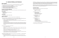
Programming Menu
Flowchart
Pro Logic
092330D RevG
Copyright © 2010 Hayward
www.haywardnet.com
620 Division St.
Elizabeth, NJ
07207
denotes conditional items
PS-4 only
PS-4 only
default menu
day and time
water temperature
air temperature
chlorinator setting
salt level
reason pump is running (not scheduled)
inspect cell
reason hi-speed is running (not scheduled)
countdown time remaining
heater control status
system manual off
check system error
group active
filter vsp speed/reason
spa filter vsp speed/reason
lights/aux speed/reason
pH/ORP levels
settings menu
spa heater1 temperature
pool heater1 temperature
spa heater2 temperature
pool heater2 temperature
spa heater2 priority
pool heater2 priority
spa solar temperature
pool solar temperature
vsp speed settings
superchlorinate
spa chlorinator setting
pool chlorinator setting
aux colorlogic settings
day and time
backlit display light
beeper
teach wireless remote
wireless channel
maintenance menu
pH calibration wizard
clean probe wizard
timers menu
pool filter 1 or hi-speed 1
pool filter 2 or lo-speed 1
pool filter 3 or hi-speed 2
pool filter 4 or lo-speed 2
spa filter 1 or hi-speed
spa filter 2 or lo-speed
spa
lights
aux1
aux2
valve3
valve4
superchlorinate
diagnostic menu
chlorinator diagnostics
instant salt
pH/orp levels
flow switch
cell temperature sensor
water/pool sensor
spa sensor
air sensor
solar sensor
vsp speed/power
main software revision
display software revision
expansion unit software revision
chemistry sense module software
vsp software revision
RF base software revision
6 button spa side software revision
digital spa side software revision
colorlogic module software revision
colorlogic light software revision
configuration menu
chlorinator
chemistry config. Wizard
pool/spa
filter
spa filter
heater1
heater2
solar
colorlogic
external input active state
lights
aux1
aux2
valve3
valve4
6 button spa side remote
digital spa side remote
remote menus
7-day or weekend/weekday timeclock
12 hour or 24 hour time format
ºF or ºC
vsp speed (% or rpm)
reset colorlogic to default
reset to default