Hayward Pro Logic Models: PL-PS-4 PL-PS-8 PL-PS-16 PL-PS-16V Installation - Page 11
Plumbing - sense & dispense
 |
View all Hayward Pro Logic manuals
Add to My Manuals
Save this manual to your list of manuals |
Page 11 highlights
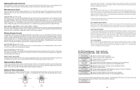
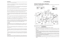
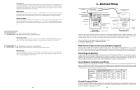
Aux1 Function Manual On/Off (default)-the aux relay will alternate between turning on and off when the aux button is pressed. There is no automatic control logic. Countdown Timer - the aux relay will turn on when the AUX button is pressed and then will turn off automatically after a programmed time (see Timers Menu in the Operations Manual). The AUX button can also be used to turn the output off. Low Speed of a 2-speed Filter Pump - the Pro Logic will operate the aux relay whenever the low speed operation of the filter pump is required. It is very important that the "2-speed" filter pump option be selected under the "Filter Config." Menu for proper operation. Timeclock - the aux relay will turn-on and turn-off at the times set for the aux timeclock in the Timers Menu (see Operations Manual). The AUX button can also be used to turn the output on and off. Solar - the aux relay operates a solar booster pump which will turn on when the filter pump is running and solar heat is available and the water is less than the desired temperature setting. It is important to note that "Solar" must be enabled in the "Solar Config." menu for proper operation to occur. Low Speed of a 2-Speed Spa Filter Pump - the Pro Logic will turn on the aux relay whenever the low speed operation of the Dual Equipment Spa filter pump is required. "Pool and Spa-Dual" (located in Pool/Spa Setup menu) and "2-Speed" (located in Spa Filter Config. menu) must be selected for proper operation. Group - the aux relay operates when the Group function is initiated and shuts off when the Group function is terminated. See Aux1 Group section for operation information for the Group function. Super Chlorinate - The Super Chlorinate function can be assigned to any Aux, Lights or Valve button. This allows the user to simply hit a button to start a Super Chlorinate cycle, rather than using the Settings Menu. Note that only one button can me assigned to this function. pH Dispense - When Chemistry Sensing is enabled and pH Reduction Control is NOT disabled, the Pro Logic will turn on the Aux relay when there is a need to energize the pH dispensing device. The pH Dispense function can be assigned to any Aux or the Lights output. Once programmed for pH Dispense, the Aux button will have no function. Requires the use of the AQL-CHEM sensing kit. Aux1 Relay This feature allows the user to select either "Standard" (default), "Dimmer", "ColorLogic" or "VSP" type relay for the Aux1 output. The optional AQL-DIM dimmer kit must be installed if "Dimmer" is desired. The AQL-COLOR-MODHV ColorLogic Network Module must be installed if "ColorLogic" is desired. When "Dimmer" is selected, and the Aux1 output is manually turned on, the "+" and "-" buttons adjust the level from 20% to 100% (default). The level is saved for the next time the aux1 output is turned from off to on. If "ColorLogic" is selected (Network Module must be detected at startup for this option to appear), additional menus will prompt you for configuration information. Refer to the AQL-COLOR-MODHV manual for details on how to configure an Aux output for use with Generation 3 or later ColorLogic lights. If "VSP" is selected, the Aux relay is used to supply power to a Hayward Variable Speed Pump (VSP). The relay will be on when the Aux output is on and off when the output is off. On, off and speed are controlled by commands sent to the VSP. Note: Up to 6 Lights/Aux outputs can be configured as VSP relays. Aux1 Interlock If "Enabled", this feature will override the function (Manual On/Off, Countdown Timer, Timeclock), selected above and turn the aux1 off when: filter pump is off, first 3 minutes of filter pump operation (allows the pump to prime and get water flowing), when the pool/spa suction return valves are in any 35 3. Plumbing "Standard" Pool/Spa system configuration These systems use a single filter pump and filter. Pool or spa operation is controlled by two 3-way valves (suction and return). Refer to the diagram below. High Voltage Relays Filter Pump Lights Aux 1 Aux 2 Valve Outputs Pool/Spa Suction Pool/Spa Return Valve 3 Valve 4 HIGH VOLTAGE LIGHTS TRANSFORMER LOW VOLTAGE LIGHTS FIBER OPTIC LIGHT SOURCE COLOR WHEEL POOL/SPA SUCTION VALVE CHECK VALVE (prevents draining of raised spas) FILTER PUMP MANUAL VALVE MANUAL VALVE POOL VACUUM VALVE TWO-WAY VALVE ENERGY FILTER ISOLATED WATER FEATURE PUMP SOLAR BOOST PUMP FILTER CHECK VALVE SOLAR VALVE SOLAR TEMPERATURE SENSOR CHECK VALVE HEATER HEAT PUMP FLOW CELL SWITCH POOL/SPA TEMPERATURE SENSOR HEATER BYPASS VALVE (manual) SPA BLOWER MANUAL VALVE POOL SWEEP BOOST PUMP POOL/SPA RETURN VALVE CHECK VALVE (prevents draining of raised spas) WATER FEATURE VALVE WATER FEATURE PUMP SPA JET PUMP SPA POP-UP IN-FLOOR CLEANER SKIM SUCTION CLEANER MAIN DRAIN ENERGY SAVER PRESSURE CLEANER SPILLOVER POOL OVERFLOW POP-UP POP-UP POP-UP RETURN JET VALVE WATER FEATURE PUMP WATER FEATURE NON-BOOST PRESSURE CLEANER PRESSURE CLEANER Some important notes regarding the Pro Logic control of Standard Pool/Spa systems: In Pool/Spa Config., select: Pool/Spa Setup Pool and Spa-Std 1. The Pro Logic can be programmed to accommodate spa spillover, if desired. 2. Up to two conventional heaters (gas or heat pump) plus solar can be used to heat both the pool and the spa. 3. If the chlorinator cell is plumbed prior to the pool/spa return valve, then both the pool and the spa can be chlorinated. 4. The water sensor should be installed prior to any heater or solar and will display either the pool or the spa temperature, depending on the current operation of the pool. The temperature will only be displayed when the filter pump is running. 5. If any water feature or pressure side cleaner boost pumps are used, be sure to enable the "interlock" feature (see "Configuration Menu" for details) to ensure that the pumps operate only when the filter pump is on and the system is in the "pool only" operating mode. 6. The plumbing diagram above is intended to be used as a general guideline and is not a complete plumbing schematic for the pool. 7. The air sensor must be installed if the freeze protection feature is enabled for the filter, valves or aux outputs. 8
-
 1
1 -
2
-
3
-
4
-
5
-
 6
6 -
 7
7 -
 8
8 -
 9
9 -
 10
10 -
 11
11 -
 12
12 -
 13
13 -
 14
14 -
 15
15 -
 16
16 -
17
-
18
-
19
-
20
-
21
-
22
-
23
-
24
 |
 |
