Hayward Pro Logic Models: PL-PS-4 PL-PS-8 PL-PS-16 PL-PS-16V Installation - Page 12
Dual Equipment - Separate Heaters for Pool/Spa configuration - light
 |
View all Hayward Pro Logic manuals
Add to My Manuals
Save this manual to your list of manuals |
Page 12 highlights
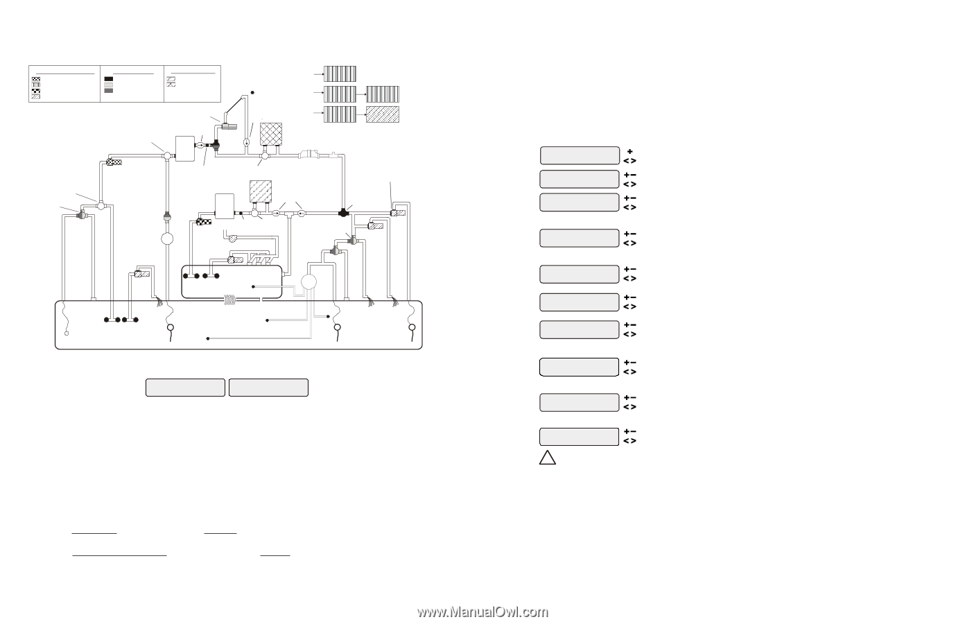
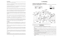
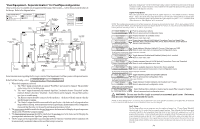
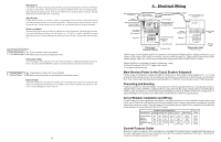
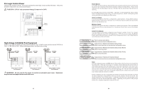
"Dual Equipment - Separate Heaters" for Pool/Spa configuration These systems have 2 complete sets of equipment (filter pump, filter, heater)-1 set for the pool and the other set for the spa. Refer to the diagram below: High Voltage Relays Pool Filter Pump Lights Spa Filter Pump (Aux 1) Aux 2 - Aux 6 Valve Outputs Pool/Spa Spillover Valve 3 Valve 4 Heater Outputs Heater 1 (Spa) Heater 2 (Pool) MANUAL VALVE SOLAR BOOST PUMP CHECK VALVE FILTER SOLAR VALVE SOLAR TEMPERATURE SENSOR CHECK VALVE HEATER HIGH VOLTAGE LIGHTS TRANSFORMER LOW VOLTAGE LIGHTS FIBER OPTIC LIGHT SOURCE COLOR WHEEL CELL FLOW SWITCH MANUAL VALVE POOL VACUUM VALVE POOL FILTER PUMP TWO-WAY VALVE ENERGY FILTER ISOLATED WATER FEATURE PUMP POOL TEMPERATURE SENSOR HEATER BYPASS VALVE (manual) FILTER HEATER CHECK VALVE (prevents draining of raised spas) SPA FILTER PUMP SPA TEMPERATURE SENSOR HEATER BYPASS VALVE (manual) SPA BLOWER POOL SWEEP BOOST PUMP POOL/SPA SPILLOVER VALVE (adjust cams as necessary for proper spillover) WATER FEATURE VALVE WATER FEATURE PUMP SPA JET PUMP SPA POP-UP IN-FLOOR CLEANER SKIM SUCTION CLEANER MAIN DRAIN ENERGY SAVER PRESSURE CLEANER SPILLOVER POOL OVERFLOW POP-UP POP-UP POP-UP RETURN JET VALVE PUMP WATER WATER FEATURE FEATURE NON-BOOST PRESSURE CLEANER PRESSURE CLEANER Some important notes regarding the Pro Logic control of Dual Equipment Pool/Spa systems with separate heaters: In the Pool/Spa Config., select: Pool/Spa Setup Pool and Spa-Dual Heaters Htr1=Spa,Htr2=Pool 1. When dual equipment is selected: a. The "Filter" pump automatically is renamed "Pool Filter" and can not be changed. The pool filter can be a one, two or variable pump. b. The "Aux1" output is automatically renamed "Spa Filter", its function is set to "Timeclock" and the Interlock feature is forced to "Disabled". None of these can be changed. The spa filter can be a one, two or variable pump. c. The Heater1 output should be connected to the spa heater-the heater will only turn on when the spa filter pump is running. d. The Heater2 output should be connected to the pool heater-the heater will only operate when the pool filter is running. If the system does not have a pool heater, disable Heater2 in the configuration menu and then the relay can be used to operate general purpose Valve4. 2. The water sensor should be installed on the pool loop prior to the heater and will display the pool temperature whenever the "Pool Filter" pump is running. 3. The dual equipment spa sensor should be installed on the spa loop prior to the heater and will display the spa temperature whenever the "Spa Filter" pump is running. 4. The Pro Logic can be programmed to accommodate spillover if desired. Note that spillover operation will be automatically suspended whenever the spa filter pump is turned on. 9 lights relay during freeze--see the "Filter Pump Config." menu to enable freeze protection for the main circulation system. Freeze Protection is not available for low speed filter pump, dimmer, group, super chlorinate or pH dispense functions. Lights Pump Speed This is the speed of the filter pump when the Lights output is on. The default selection is "Settings Menu". This is the speed of the pump that has been selected in the Settings Menu for normal filter operation. If an alternate speed is desired when the Lights output is on, push "+" or "-" and select from "Filter Lowest" to "Filter Highest" in 5% increments. NOTE: The configuration parameters for all Aux outputs are the same as shown below for Aux1. PS-4: Aux1 and Aux2. PS-8: Aux1 through Aux6. PS-16: Aux1 through Aux14. Also note that for the PS-16, Valves7, 8, 9 and 10 are turned On/Off with the control function selected for Aux7, 8, 9, and 10, respectively. Aux1 Config. + to view/change Push to access Aux options Move to previous/next configuration menu Aux1 Name Cleaner Rotates between all available names Move to next menu item Aux1 Function Manual On/Off for manual on/off, countdown timer and timeclock functions Aux1 Relay Standard Rotates between Manual On/Off (default), Countdown Timer, Low Speed- Filter, Timeclock, Solar, Low Speed-Spa Filter, Group, Super Chlorinate, and pH Dispense Move to next menu item Toggle between Standard (default), Dimmer, ColorLogic and VSP Move to next menu item or previous/next configuration menu for all functions except solar, dimmer relay,super chlorinate low speed, group and pH dispense Aux1 Interlock Toggle between Enabled and Disabled (default) Aux1 Interlock Disable Move to next menu item for group function only Aux1 Group Timer: None(Manual) Rotates between Manual On/Off (default),Countdown Timer and Timeclock Move to next configuration menu item for group function only Aux1 Group Filter: Unaffected Options available depend on the function that is selected Move to previous/next menu item or next configuration menu for all functions except solar, dimmer relay,super chlorinate low speed, group and pH dispense Aux1 Ext Input Toggle between Enabled and Disabled (default) Disabled Move to previous/next configuration menu for all functions except dimmer relay, super chlorinate low speed, group and ph dispense Aux1 Freeze Toggle between Enabled (default) and Disabled Aux1 Freeze Disable Move to previous/next configuration menu if filter pump is set to variable speed and the relay type is set to standard Aux1 Pump Spd Select Settings Menu (default) or desired pump speed (Filter Lowest to Highest) Settings Menu Move to previous/next configuration menu ! WARNING: Do not use the Pro Logic to control an automatic pool cover. Swimmers may become entrapped underneath the cover. NOTE: If "Pool and Spa-Dual" is selected, Aux1 is dedicated to use as the spa filter. Its Name is set to Spa Filter, the Function is set to Timeclock and Interlock is set to Disabled. These can't be changed. Aux1 Name The Pro Logic allows you to assign any one of a number of names (e.g. "Cleaner Pump, Waterfall, Gazebo Light, etc.) to each of the aux outputs control function. This will make the Pro Logic much more user friendly to the homeowner when they want to turn various aux equipment on or off or program the timeclocks. A sheet of small name labels is included with the Pro Logic main unit and each remote display/keypad so that the "Aux" pushbutton can be labeled the same as the name that you have assigned. At this time it is also a good idea to make sure that the relay in the control box is also labeled (hand written) with the same name as a help to technicians who may service this system at a later date. 34
-
 1
1 -
2
-
3
-
4
-
5
-
6
-
 7
7 -
 8
8 -
 9
9 -
 10
10 -
 11
11 -
 12
12 -
 13
13 -
 14
14 -
 15
15 -
 16
16 -
 17
17 -
18
-
19
-
20
-
21
-
22
-
23
-
24
 |
 |