Hayward Pro Logic Models: PL-PS-4 PL-PS-8 PL-PS-16 PL-PS-16V Installation - Page 24
Configuration Setup - 8 panels
 |
View all Hayward Pro Logic manuals
Add to My Manuals
Save this manual to your list of manuals |
Page 24 highlights
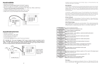
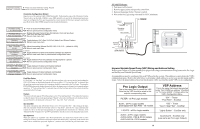
Flow Switch Only applicable if the chlorinator function is enabled and/or the flow monitor feature is desired. The flow switch cable plugs into the Pro Logic Control Center as shown in the diagram on page 12. Ensure that the connector catch "snaps" in order to provide a reliable connection. Turbo Cell Only applicable if the chlorinator function is enabled. The Turbo Cell should be plugged in after the Pro Logic cover panel is put back in place. Refer to page 12 for the location of the connector. External Input Interlock The External Input Interlock provides a means to force the filter pump or an Aux output off when certain conditions exists. A normally open or normally closed on/off external device must be connected to the Pro Logic as shown below. After properly configuring the Pro Logic (see Configuration), the filter pump and/or desired Aux will be forced off when the device is active. SPST External Switch (either Normally Open or Normally Closed) Hayward Aqua Rite Chlorinator The Pro Logic can control one or more Hayward Aqua Rite chlorinators when additional sanitizing capacity is required. A 4 wire connection is used to communicate to the Aqua Rite and can be wired up to 500' apart. Any outdoor rated 4 conductor cable can be used. Refer to the wiring diagrams below for proper wiring connection to the Aqua Rite. NOTE: There must be only 1 "primary" unit. All other Aqua Rite units must be configured as "secondary". Jumper Installed For Primary (Factory Default) Pro Logic Aqua Rite (Primary) 4 GREEN 3 YELLOW 2 BLACK 1 RED Jumper Removed For Secondary(s) Aqua Rite (Secondary) Additional Aqua Rite(s) (if required) NOTE: Primary/Secondary jumper is located underneath small circuit board. Pro Logic GRN 4 YEL 3 BLK 2 RED 1 green 4 GRN Aqua Rite yellow bl ack 3 YEL 2 BLK red 1 RED 21 5. Configuration Setup After plumbing and wiring are complete, the Pro Logic MUST BE CONFIGURED before attempting to operate. Configuration information is entered at the keypad and "tells" the Pro Logic what equipment is connected and how each should be controlled. Group Function The latest version of the Pro Logic offers the ability to assign a Group function to a particular button. Instead of a button controlling one particular function, the button can be programmed to initiate a sequence of commands that are programmed in the Configuration Menu. For example, instead of the Lights button turning on and off the pool light only, the button can be programmed to turn on the pool light, turn on the bug light, turn off the pool cleaner, turn on and dim the patio lights, turn on the music, etc. all at the same time. This convenient feature is offered on all Aux buttons, both Valve buttons and the Lights button. The Pro Logic can be programmed to control up to four groups. Refer to this section when programming Group commands. Before assigning and configuring all the desired functions and their control parameters, the group itself must be configured. The options for controlling groups are Manual On/Off, Countdown Timer, and Timeclock. The group will turn on and off based on this selection. When setting up a Group function in the Configuration Menu, the first menu allows you to select the control parameter (how the group is activated and de-activated) and the second menu allows you to select which Pro Logic functions are to be controlled in the group. A table of functions and their corresponding control parameters are listed below. Function Pool/Spa Pool Filter Lights (standard relay) Lights (dimmer relay) Lights (VSP relay) Spa Filter Aux1-14 (standard relay) Aux1-14 (dimmer relay) Aux1-14 (VSP relay) Valve3 Valve4 Spa Htr1 Set Pool Htr1 Set Spa Htr2 Set Pool Htr2 Set Spa Solar Set Pool Solar Set SuperChlr Control Parameter Unaffected, Pool only, Spa only, or Spillover Unaffected, Off, On, High, Low, On (Lowest to Highest) Unaffected, Off, or On Unaffected, Off, On (100%, 80%, 60%, 40%, or 20%) Unaffected, Off or On (10% to 100%) Unaffected, Off, On, High, Low, On (Lowest to Highest) Unaffected, Off or On Unaffected, Off, On (100%, 80%, 60%, 40%, or 20%) Unaffected, Off or On (10% to 100%) Unaffected, Off or On Unaffected, Off or On Unaffected, Off, 65º-104ºF Unaffected, Off, 65º-104ºF Unaffected, Off, 65º-104ºF Unaffected, Off, 65º-104ºF Unaffected, Off, 65º-104ºF Unaffected, Off, 65º-104ºF Unaffected, Off, On 22
-
 1
1 -
2
-
3
-
4
-
5
-
6
-
7
-
8
-
9
-
10
-
11
-
12
-
13
-
14
-
15
-
16
-
17
-
18
-
 19
19 -
 20
20 -
 21
21 -
 22
22 -
 23
23 -
 24
24
 |
 |