Hayward Pro Logic Models: PL-PS-4 PL-PS-8 PL-PS-16 PL-PS-16V Installation - Page 19
Lars Heaters, Hayward Heaters - board
 |
View all Hayward Pro Logic manuals
Add to My Manuals
Save this manual to your list of manuals |
Page 19 highlights
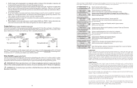
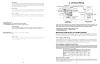
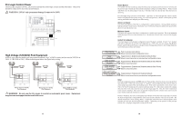
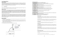
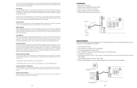
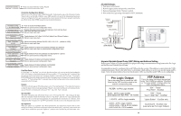
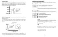
they want to control the filter equipment. A sheet of small name labels is included with the Pro Logic main unit and each remote display/keypad so that appropriate pushbuttons can be labeled the same as the name that you have assigned. Filter Pump For 2-speed pumps: When a 2-speed pump is configured, one of the AUX relays must also be configured to control the low speed motor winding on the pump. Refer to the appropriate sections in the Installation manual for specific information regarding the control logic for 2-speed and variable speed pump operation. For the Hayward variable speed pump: The Filter relay is used to supply input power to the pump. The relay will be on when the filter pump output is on. When the filter pump output is off, the relay will be off. On , off and speed is controlled by commands sent to the pump. Lowest Speed This is the lowest speed that the variable speed pump is allowed to run at. It is used as the lower limit in the Low Speed Settings Menu. Set lowest speed from 10% (default) to 50%. Highest Speed This is the highest speed that the variable speed pump is allowed to run at. It is used as the upper limit in the High Speed Settings Menu. Also, this is the speed that the pump will run at during the first 3 minutes of operation anytime the pump has been off for more than 30 seconds. Set highest speed from 20% to 100% (default). Flow Monitor This feature will help protect the filter pump from damage due to no flow. When used with a Hayward flow switch, the Pro Logic monitors the state of water flow when the filter pump is on. If no flow is detected for more than 15 minutes, the Pro Logic will shut down the pool pump and the "Check System" LED will indicate an error. The error will be cleared the next time the pump is turned on. Freeze Protection Freeze protection is used to protect the pool and plumbed equipment against freeze damage. If freeze protection is enabled and the AIR temperature sensor falls below the freeze threshold (see below), the Pro Logic will turn on the filter pump to circulate the water. If "Pool and Spa" is selected in the Pool/ Spa sub-menu (see page 18), the valves will also alternate between the pool and spa every 30 minutes and the filter pump will turn off while the valves are turning. The chlorinator will not operate if freeze protection is the only reason the pump is running. Freeze Protection Speed This menu only appears if freeze protection is enabled and the pump is configured for 2-speed or variable speed pump operation. If the pump turns on due to freeze protection only, the pump will run at this speed. 2-Speed pumps: Select high (default) or low speed operation. Variable Speed pumps: Select the desired speed (from Filter Lowest to Filter Highest speed). Freeze Protection Temperature Select the temperature to be used for freeze protection. Temperature is adjustable from 33ºF-42ºF (1ºC6ºC). 38ºF (3ºC) is default. This threshold will be used for all outputs that have freeze protection enabled. External Input Interlock When enabled, the filter pump will be forced off when the external input is active. Note that freeze protection will have precedence over this feature. 27 Lars Heaters 1. Turn power off to heater. 2. Remove factory jumper from terminal block. 3. Wire Pro Logic to the heater as shown. 4. Ensure toggle switch is in the ON position. 5. Set heater thermostats to maximum position. to limit switches white remove jumper white Fusible Link Hayward Heaters Refer to the instructions in the heater manual for "2-wire Remote Thermostat" operation under "Remote Control Connections" and the diagram on the below: 1. Turn off power to heater. 2. Wire Pro Logic to terminals 1 & 2 (see diagram). 3. Leave jumper attached to terminals 4 & 5. 4. Move "BYPASS" dipswitch on heater circuit board to "ON" position (up). 5. Turn heater power back on. 6. Switch heater to either "Pool" or "Spa" (it doesn't make any difference which is selected, the Pro Logic will take control). 7. Heater display should be "bO" (for "bypass On). 8. Heater will fire whenever Pro Logic requests (when Pro Logic "Heater" LED is illuminated). ºC ON ºF OFF Dipswitch located on heater circuit board PK W R BK R Terminal block located at electrical junction box Do not remove jumper 16
-
 1
1 -
2
-
3
-
4
-
5
-
6
-
7
-
8
-
9
-
10
-
11
-
12
-
13
-
 14
14 -
 15
15 -
 16
16 -
 17
17 -
 18
18 -
 19
19 -
 20
20 -
 21
21 -
 22
22 -
 23
23 -
 24
24
 |
 |