Hayward Pro Logic Models: PL-PS-4 PL-PS-8 PL-PS-16 PL-PS-16V Installation - Page 16
Pro Logic Control Power, High Voltage 120/240V Pool Equipment - wiring
 |
View all Hayward Pro Logic manuals
Add to My Manuals
Save this manual to your list of manuals |
Page 16 highlights
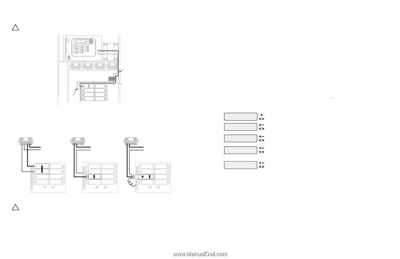
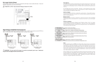
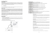
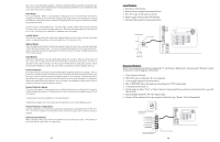
Pro Logic Control Power The Pro Logic requires 120VAC, 2A power to operate the control logic circuits and the chlorinator. This power should be connected to one of the circuit breakers. ! WARNING: 120VAC only (permanent damage if connected to 240V) Field Wired 120, 2VA Factory Prewired Neutral L1 High Voltage (120/240V) Pool Equipment All Pro Logic relays are double pole (they make/break both "legs" of 240V circuits) and are rated at 3HP/30A at 240V (1½HP/30A at 120V). Refer to the diagram below for typical relay wiring. 240 VAC Load 120 VAC Load 120 VAC Load Wiring relays for 240 VAC Pool Equipment Wiring relays for 120 VAC Pool Equipment Wiring GFCB for 120 VAC Pool Equipment ! WARNING: Do not use the Pro Logic to control an automatic pool cover. Swimmers may become entrapped underneath the cover. 13 Heater Extend If "Enabled", the filter extend logic keeps the filter pump running beyond the normal turn-off time until the pool (or spa) is heated up to the desired temperature setting (see Settings Menu). Heater extend will NOT cause the filter pump to turn on, it will only delay the turn off time when the heater is operating. For a Pool/Spa Setup selection of "Pool Only", "Spa Only" or "Pool and Spa-Std", Heater1 and/or Heater2 will keep the filter pump running. For "Pool and Spa-Dual", Heater1 will keep the spa filter running and Heater2 will keep the pool filter running. Allow Low Speed This menu only appears if the filter is configured for 2-speed operation. During default operation, high speed mode is used whenever the heater is on. If Allow Low Speed is enabled, low speed will be allowed even if the heater is on. Minimum Speed This menu only appears if the filter is configured for variable speed operation. This is the minimum speed the pump will run at when the heater is on. The selection is from Filter Lowest to Filter Highest speed. Heater2 is Heatpump This menu appears in the Heater2 configuration menu if Heater2 is enabled. If set to "Yes", Heater2 will only be allowed to be on if the Air Temperature is > 50°F. Also, two new menus, Spa Heater2 Priority and Pool Heater2 Priority, will appear in the Settings Menu. Refer to the Settings Menu for more information on these new menus. Solar Config. + to view/change Solar Disabled if "Solar" is enabled Solar-Extend Disabled if "Solar" is enabled Solar Priority Disabled if "Solar" is enabled and "2-speed Filter" is selected Allow Low Speed Disabled Push to access solar options Move to previous/next configuration menu Toggle between Enabled and Disabled (default) Solar Move to next menu item or previous/next configuration menu Toggle between Enabled and Disabled (default) Solar Extend Move to next menu item Toggle between Enabled and Disabled (default) Solar Priority Move to next menu item Toggle between Enabled and Disabled (default) Move to next menu item or previous/next configuration menu Solar The Solar configuration menu will NOT appear if "Pool and Spa - Dual" has been selected in the Pool/ Spa setup menu. If the solar control logic is "Enabled", several additional steps must be taken to ensure proper operation of the solar heating system. If the solar is operated by a valve, then a valve (Valve3 or Valve4) output must be setup for solar logic (page 37). If the solar is operated by a pump, then one of the AUX relays must be set up for solar logic (page 34). Also, the "solar" temperature sensor must be installed. This sensor is typically mounted near the collector array and is used to sense whether sufficient solar heat is available. If solar is "Enabled", the valve or solar pump relay will turn on when the water temperature is less than the desired temperature setting AND the solar sensor is hotter than the water by at least 8ºF. The desired temperature is in the "Settings Menu". If applicable, the homeowner will be prompted to enter separate pool and spa desired temperature settings. Depending on the position of the pool/spa suction valve, the proper temperature setting will be used. 30
-
 1
1 -
2
-
3
-
4
-
5
-
6
-
7
-
8
-
9
-
10
-
 11
11 -
 12
12 -
 13
13 -
 14
14 -
 15
15 -
 16
16 -
 17
17 -
 18
18 -
 19
19 -
 20
20 -
 21
21 -
22
-
23
-
24
 |
 |