Hayward Pro Logic Models: PL-PS-4 PL-PS-8 PL-PS-16 PL-PS-16V Installation - Page 18
Low Voltage Wiring - remote control
 |
View all Hayward Pro Logic manuals
Add to My Manuals
Save this manual to your list of manuals |
Page 18 highlights
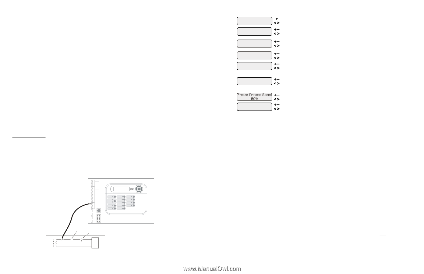
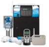
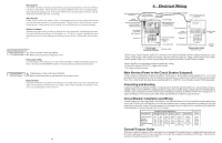
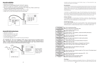
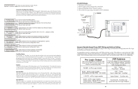
Low Voltage Wiring Valve Actuators The Pro Logic can control up to four (PS-4/8) or eight (PS-16) 24V automatic valve actuators. Two of the valve outputs are dedicated to the pool/spa suction (Valve2) and return (Valve1) valves. Valve3 and Valve4 (Valves3, 4, 7-10 for PS-16) are for general purpose use (solar, water feature, in-floor cleaner, etc.). For installations with solar heating, Hayward offers the AQ-SOL-KIT-xx solar kit that contains a valve, actuator, and extra temperature sensor. The "xx" indicates the valve type from the 2 choices below: -1P 1.5" Positive Seal -2P 2" Positive Seal The Pro Logic is compatible with standard valve actuators manufactured by Hayward, Pentair/Compool, and Jandy. See diagram on page 12 for the location of valve connectors. Heater Control The Pro Logic allows for independent control of up to 2 heaters plus a solar heating system if applicable. A typical use for this feature is on a pool that has both a gas heater (for rapid heating of the spa) and a heat pump (for economical heating of the pool). IMPORTANT: If you chose to use the "Heater2" control output, then you will not be able to use the "Valve4" output. These 2 functions use the same internal relay and only one can be enabled. In the configuration menu, if "Heater2" is enabled, then the configuration for "Valve4" will never appear. The heater interface wiring, as described below, is identical for "Heater1" and "Heater2" except for the terminal connections at the Pro Logic control. The Pro Logic provides a set of low voltage dry contacts that can be connected to most gas heaters or heat pumps with 24V control circuits. Refer to the diagram on the following page for a generic connection. The manuals supplied with most heaters also include specific wiring instructions for connecting the heater to an external control (usually identified as "2-wire" remote control). For millivolt or line voltage heaters, contact Hayward Tech support, 908-355-7995. Refer to the diagrams and the information on the following pages for more details on the connection to several popular heaters. Generic Heaters 1. Wire heater to 120/240V power source per the instructions in the heater manual. The Pro Logic does NOT control the power going to the heater. 2. Wire the Pro Logic dry contact heater output per the diagram below. Many internal parts of the heater can get very hot--see the heater manufacturer's recommendations on the minimum temperature rating for wires. If no guidance is given, use 105°C rated wire. 3. Set any ON/OFF switch on the heater to ON. 4. Set the thermostat(s) on the heater to the maximum (hottest) setting. Kill Switch Thermostat Heater Ignition/Valve 15 if "Pool & Spa Dual" is selected Spa Filter Config. + to view/change Push to access Spa Filter options Move to previous/next configuration menu item Spa Filter Pump 1 Speed if "Variable Speed" is selected Lowest Speed 10% if "Variable Speed" is selected Highest Speed 100% Rotates between 1-speed (default), 2-speed and variable speed options Move to next menu item Adjust the lowest speed desired for variable speed operation Move to next menu item Adjust the highest speed desired for variable speed operation Move to next menu item Freeze Protect Enabled if "Freeze Protect" is enabled and "2-speed Filter" is selected Freeze Protect High Speed if "Freeze Protect" is enabled and "Variable Speed" is selected External Input Disabled Toggle between Enabled (default) and Disabled Freeze Protection Move to next menu item or previous/next configuration menu Toggle between high speed (default) and low speed Move to next menu item Select the desired Freeze Protection speed from Spa Filter Lowest to Highest speed Move to next menu item Toggle between Enabled and Disabled (default) Move to previous/next configuration menu Spa Filter Pump For 2-speed pumps: When a 2-speed pump is configured, one of the AUX relays must also be configured to control the low speed motor winding on the pump. Refer to the appropriate sections in the Installation manual for specific information regarding the control logic for 2-speed and variable speed pump operation. For the Hayward variable speed pump: The Spa Filter (Aux1) relay is used to supply input power to the pump. The relay will be on when the filter pump output is on. When the filter pump output is off, the relay will be off. On , Off and speed is controlled by commands sent to the pump. Lowest Speed This is the lowest speed that the variable speed pump is allowed to run at. It is used as the lower limit in the Spa Low Speed Settings Menu. Set lowest speed from 10% (default) to 50%. Highest Speed This is the highest speed that the variable speed pump is allowed to run at. It is used as the upper limit in the Spa High Speed Settings Menu. Also, this is the speed that the pump will run during the first 3 minutes of operation anytime the pump has been off for more than 30 seconds. Set highest speed from 20% to 100% (default). Freeze Protection Freeze protection is used to protect the spa and plumbed equipment against freeze damage. If freeze protection is enabled and the AIR temperature sensor falls below the freeze threshold (selectable in Filter Configuration Menu - page 26), the Pro Logic will turn on the spa filter pump to circulate the water. Freeze Protection Speed This menu only appears if freeze protection is enabled and the pump is configured for 2-speed or variable speed pump operation. If the pump turns on due to freeze protection only, the pump will run at this speed. 2-Speed pumps: Select high (default) or low speed operation. Variable Speed pumps: Select the desired speed (from Filter Lowest to Filter Highest speed). 28
-
 1
1 -
2
-
3
-
4
-
5
-
6
-
7
-
8
-
9
-
10
-
11
-
12
-
 13
13 -
 14
14 -
 15
15 -
 16
16 -
 17
17 -
 18
18 -
 19
19 -
 20
20 -
 21
21 -
 22
22 -
 23
23 -
24
 |
 |