Hayward Pro Logic Models: PL-PS-4 PL-PS-8 PL-PS-16 PL-PS-16V Installation - Page 22
Accessing the Configuration Menus, Configuration Menus - aqua connect
 |
View all Hayward Pro Logic manuals
Add to My Manuals
Save this manual to your list of manuals |
Page 22 highlights
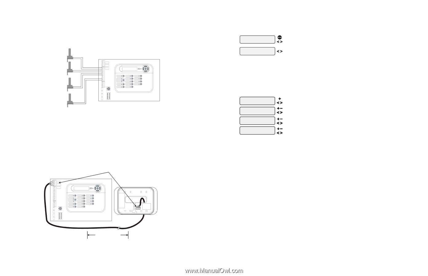
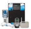
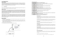
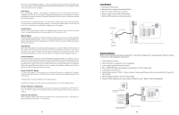
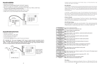
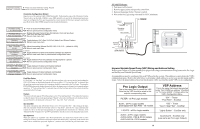
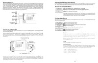
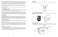
Temperature Sensors The Pro Logic utilizes 10K ohm thermistor type sensors. Three sensors (water temperature, air temperature and solar or dual equipment spa temperature) are included. If the Pro Logic is being used to control a solar heating system, the solar sensor is required. If dual equipment will be used, the dual equipment spa sensor (spa temperature for "Pool and Spa-Dual") is required. If both solar and dual equipment are desired, another temperature sensor must be purchased separately. The sensors are provided with a 15 ft. cable. If a longer cable is required, contact the Hayward service dept. (908-355-7995) for information on suitable cable types and splices. See Temperature Sensors on page 6 for directions on installing sensors. POOL/SPA SENSOR AIR SENSOR SOLAR SENSOR optional DUAL EQUIPMENT SPA SENSOR optional Wired Remote Display/Keypad The Pro Logic main unit can connect to a maximum of 3 remote wired display/keypads. Wired display/keypads must be ordered separately. Use four conductor cable (typically phone cable) to connect the wired remote display/keypad with the Pro Logic Control Center as shown below. The maximum wiring distance is 500ft. (160m). Note that the terminals on both the Pro Logic main unit and the wired remote display/keypad are numbered: Connect 1 to 1, 2 to 2, etc. Refer to diagram below. Connect screw terminals "1" to "1", "2" to "2", etc. Wired Remote Display unit 432 1 500 ft max If multiple remote display/keypads are installed: Never connect more than 2 wires to any terminal block. Two remotes can be wired back to the Pro Logic main unit or the second display/keypad (and third, if applicable) can be "daisy chained" with one display/keypad wired to the next. The maximum wire run from the Pro Logic main unit to the furthest remote display/keypad is 500 ft (160m). 19 Accessing the Configuration Menus Configuring the Pro Logic requires that you navigate through the Configuration Menu and input various information. For more detailed information about using the Pro Logic menu system, refer to the Operation Manual. To access the Configuration Menus Configuration Menu-Locked Configuration Menu-Unlocked Press repeatedly until "Configuration Menu" is displayed Press BOTH buttons SIMULTANEOUSLY for 5 seconds to unlock Move to configuration menu items NOTE: The configuration menu automatically "locks" after 2 minutes of no buttons being pressed to prevent unauthorized people from changing the control logic inadvertently and possibly damaging the pool equipment or causing a "call back" to fix the configuration. Configuration Menus Each item needs to be programmed and may contain additional sub-menu items. Refer to the following pages for information on programming. Chlor. Config. + to view/change Chlorinator Enabled Display Salt Cell Type T-CELL-15 Push to access Chlorinator option Move to next configuration menu Toggle between Chlorinator Enabled and Disabled (default) Move to next menu item Toggle between Display Salt (default) and Minerals Move to previous/next configuration menu Rotates between available Cell types Move to next menu item Chlorinator Requires the use of a chlorinator cell and P-KIT sold separately. If the chlorinator is enabled, then the cell and flow switch must also be installed and the Pro Logic will automatically chlorinate both the pool and spa according to the desired output setting (see Settings Menu in the Operation manual). If disabled (default), all displays relating to the chlorinator will be suppressed. When the chlorinator is enabled, the Pro Logic will automatically detect and control any Aqua Rite(s) that is installed in the system. Display Allows for the display of salt (default) or mineral values. Cell Type Selection The Cell Type Menu appears after "Display Salt/Minerals" in the Chlorinator Configuration Menu. The options are T-CELL-15 (default), T-CELL-9, T-CELL-5 or T-CELL-3. Make the proper selection based on the chlorinator cell that is used in your system. Refer to the information below. "T-CELL-3" = T-CELL-3, GLX-CELL-3-W "T-CELL-5" = GLX-CELL-5, GLX-CELL-5-W "T-CELL-9" = T-CELL-9, GLX-CELL-9-W "T-CELL-15" = T-CELL-15, GLX-CELL-15-W 24
-
 1
1 -
2
-
3
-
4
-
5
-
6
-
7
-
8
-
9
-
10
-
11
-
12
-
13
-
14
-
15
-
16
-
 17
17 -
 18
18 -
 19
19 -
 20
20 -
 21
21 -
 22
22 -
 23
23 -
 24
24
 |
 |