Hayward Pro Logic Models: PL-PS-4 PL-PS-8 PL-PS-16 PL-PS-16V Installation - Page 5
System S, artup and Checkout - control
 |
View all Hayward Pro Logic manuals
Add to My Manuals
Save this manual to your list of manuals |
Page 5 highlights
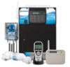
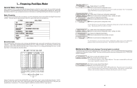
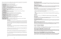
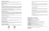
6. System Startup and Checkout Before Startup Before starting the Pro Logic for the first time, be sure that the following items have been completed: 1. Pool/spa chemicals are within the recommended levels according to the chart on page 3. 2. Pool/spa salt level is between 2700 - 3400 PPM. 3. Properly rated circuit breakers are installed in the Pro Logic subpanel. 4. All wiring is performed according to NEC and local codes. 5. The Pro Logic is properly grounded and bonded. 6. The Pro Logic is properly configured to control all desired functions. Program Automatic Operation Refer to the programming flow chart on the back cover of this manual for a listing of the available menus and the items included in each menu. Settings Menu Heater(s) and/or solar thermostat settings Chlorinator settings Day and Time Timers Menu Timeclock and/or Countdown timer settings Heater Checkout Follow these instructions to verify that the Pro Logic is properly controlling the heater. 1. Check that the Pro Logic is calling for the heater to turn on as indicated by the "Heater" LED being illuminated. If the "Heater" LED is illuminated, go directly to step 2; if not, then check the following: • The heater is enabled (Configuration Menu/Heater Config.). • The heater temperature setting is at least 2ºF greater than the water temperature (Settings Menu / Pool Heater & Spa Heater). • The filter pump is running. • If the pool has solar heat and the solar priority feature is enabled (Configuration Menu/Solar Config) then solar must be off in order for the heater to fire. The easiest way to force solar off is to go to the Settings Menu / Pool Solar & Spa Solar and temporarily lower the temperature settings below the current water temperature. 2. Check that the heater is running. If not, then check: • Power is supplied to the heater. • The Pro Logic control output is properly connected to the heater control (see "Heater Control" wiring, page 15). • Some heaters also have internal switches or jumpers that have to be set correctly for remote control operation-refer to the heater manual and also "Heater Control" (page 15). • Heater is turned on ("Kill Switch" is in the "ON" position). • If a heater bypass valve is installed, check that water is flowing through the heater. • The heater temperature setting is set as high as possible (usually 104ºF/40ºC). Also note that some heat pumps actually have be set to the lowest possible temperature. 3. Once the heater is running, you can verify the "heater cooldown" feature (optional - see Configuration Menu/ Heater Config.) is operating properly: • Press the "Filter" button once (for 2 speed pumps, this may require 2 pushes of the "Filter" button). • The heater should turn off ("Heater" LED off) and the "Filter" LED will flash to indicated heater cooldown is active. 41 NOTE: Before installing this product as part of a saline water purification system in a pool or spa using natural stone for coping or for immediately adjacent patios/decking, a qualified stone installation specialist should be consulted regarding the appropriate type, installation, sealant (if any) and maintenance of stone used around a saline pool with electronic chlorine generator in your particular location and circumstances. NOTE: The use of dry acid (sodium bisulfate) to adjust pool pH is discouraged especially in arid regions where pool water is subject to excessive evaporation and is not commonly diluted with fresh water. Dry acid can cause a buildup of by-products that can damage your chlorinator cell. Installation Steps Details on each installation step are presented on the following pages: 1. Prepare the pool water (page 3) General Water Chemistry Salt 2. Mounting the equipment (page 5) Pro Logic main unit Temperature sensors Remote display/keypad (optional) Valve actuators (if applicable) 3. Plumbing (page 8) General Pool Equipment Chlorinator Turbo Cell Flow Switch 4. Electrical Wiring (page 12) Main service Grounding and bonding Circuit breakers Pro Logic control power High Voltage pool equipment Low voltage wiring (temperature sensors, flow switch, etc.) 5. Pro Logic control configuration (program desired control operation) (page 22) 6. System Startup and checkout (page 41) 2
-
 1
1 -
 2
2 -
 3
3 -
 4
4 -
 5
5 -
 6
6 -
 7
7 -
 8
8 -
 9
9 -
 10
10 -
 11
11 -
12
-
13
-
14
-
15
-
16
-
17
-
18
-
19
-
20
-
21
-
22
-
23
-
24
 |
 |