Hayward Pro Logic Models: PL-PS-4 PL-PS-8 PL-PS-16 PL-PS-16V Installation - Page 17
Hayward Variable Speed Pump - software
 |
View all Hayward Pro Logic manuals
Add to My Manuals
Save this manual to your list of manuals |
Page 17 highlights
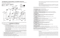
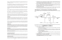
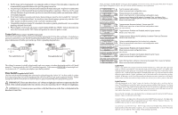
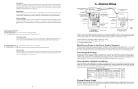
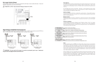
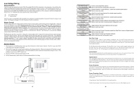
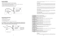
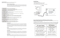
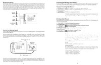
External Input When enabled, the filter pump will be forced off when the external input is active. Note that freeze protection will have precedence over this feature. NOTE: Heater1 and Heater2 configuration are identical. If Heater2 is enabled then Valve4 will automatically be disabled due to the fact that they use the same output relay and only 1 function can be assigned to that relay. Heater1 Config. + to view/change Push to access heater options Move to previous/next configuration menu Heater1 Disable Toggle between Enabled and Disabled (default) Heater 1 Move to next menu item or previous/next configuration menu if "Heater1" is enabled Heater1 Name Gas Heater Rotates between all available names Move to next menu item if "Heater1" is enabled Heater1 Cooldown Disabled Toggle between Enabled and Disabled (default) Heater 1 Cooldown Move to next menu item if "Heater1" is enabled Heater1 Extend Disabled if "Heater1" is enabled and 2-speed filter pump is selected Allow Low Speed Disabled Toggle between Enabled and Disabled (default) Heater 1 Extend Move to previous/next configuration menu Toggle between Enabled and Disabled (default) Move to next menu item or previous/next configuration menu if "Heater1" is enabled and variable speed filter pump is selected Minimum Speed Select the desired minimum filter pump speed for Heater 1 (Filter Lowest to Highest) 50% Move to next menu item or previous/next configuration menu display for Heater2 if "Heater2" is enabled Toggle between Enabled and Disabled (default) No Move to previous/next configuration menu Heater1 If the heater is "Enabled", the heater relay will turn on when the water temperature is less than the desired temperature setting and the filter pump is running. The desired temperature is in the "Settings Menu". If applicable, the homeowner will be prompted to enter separate "pool" and "spa" settings. Depending on the position of the pool/spa suction valves, the proper temperature setting will be used. Heater Name The Pro Logic allows you to assign any one of a number of names (e.g. "Gas Heater, Heat Pump, etc.) to each of the heater control functions. This will make the Pro Logic much more user friendly to the homeowner when they want to turn various heaters on or off or set temperatures. A sheet of small name labels is included with the Pro Logic main unit and each remote display/keypad so that appropriate pushbuttons can be labeled the same as the name that you have assigned. Heater Cooldown This feature ensures that the heater cools down before water circulation is stopped. When enabled, the Pro Logic will continue to run the filter pump for 5 minutes after the heater turns off. During this period the filter pump LED will flash and also a "Heater Cooldown, X:XX remaining" message will scroll on the display. When the filter pump is running and the heater is on: Pressing the "Filter" button once will cause the heater to turn off, but the filter pump will continue to run for heater cooldown (filter LED flashing and message on display). Pushing the filter button a second time will override the heater cooldown operation and turn the filter pump off. For a Pool/Spa Setup selection of "Pool Only", "Spa Only" or "Pool and Spa-Std", Heater1 and/or Heater2 cooldown affect the filter pump. For "Pool and Spa-Dual", Heater1 is associated with the spa filter and Heater2 with the pool filter. 29 Two speed filter pump: Requires 2 relays (FILTER plus one of the AUX relays) for proper operation of both speeds. ! IMPORTANT: Be sure to follow the wiring diagram below AND to configure the control logic according to the instructions on page 26. Lo Speed Hi Speed Common Ground 2-Speed Filter Pump N L2 L1 G Lights: A ground fault circuit breaker must be used to supply power for high voltage pool/spa lighting. Low voltage lights will require an external transformer. For lighting systems that have both a light source and color wheel, connect the light source to the "Lights" relay and then connect the color wheel to one of the AUX outputs. ColorLogic networked pool/spa lights require the installation of an AQL-COLOR-MODHV and unique wiring. Refer to the AQL-COLOR-MODHV manual for detailed installation and wiring information. Hayward Variable Speed Pump: Proper installation of a Hayward Variable Speed Pump (VSP) includes high voltage input wiring, low voltage communication wiring, and menu configuration/settings. The Pro Logic can control up to 2 Hayward TriStar VSPs and 8 EcoStar VSPs. Refer to the diagram below for proper input wiring to the VSP. Wiring from the 220V breaker must connect through the Pro Logic's Filter/Lights/Aux relay. Refer to VSP Address Setting on page 18 to determine which relays can be used with your pump. The selected relay will supply input power to the VSP pump control and be on when the output is on. When the output is off, the relay will be off. Note that when the relay is off (power off to the VSP), the Pro Logic will not display errors or diagnostics for the pump. The relay must be on for diagnostic function. Refer to the VSP manual(s) for detailed wiring information. 220 VAC input power to VSP pH Dispense Output: NOTE: The Pro Logic can only be used with a 120VAC pH dispensing device. There are two Pro Logic versions that require different installation techniques. Pro Logics operating with a software version less than 4.00 require the pigtail or pH dispensing device to be connected to an internal relay. Units using version 4.00 or later have a dedicated pH output through the screw terminals mounted on the inside of the enclosure (shown on page 12). Refer to the AQL-CHEM's pH dispense wiring instructions that relates to your particular version. Hayward ColorLogic Network Module: Refer to the AQL-COLOR-MODHV manual for detailed installation and wiring information. 14
-
 1
1 -
2
-
3
-
4
-
5
-
6
-
7
-
8
-
9
-
10
-
11
-
 12
12 -
 13
13 -
 14
14 -
 15
15 -
 16
16 -
 17
17 -
 18
18 -
 19
19 -
 20
20 -
 21
21 -
 22
22 -
23
-
24
 |
 |
