Hayward Variable Speed Pump Owners Manual - Page 11
Remote Control Wiring/Operation, SVRS Notes Only applicable to model SP3400VSPVR, WARNING - settings
 |
View all Hayward Variable Speed Pump manuals
Add to My Manuals
Save this manual to your list of manuals |
Page 11 highlights
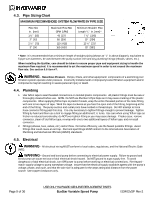
4.10. Remote Control Wiring/Operation EcoStar can be controlled in a wide variety of ways as described below: 1. EcoStar can operate by itself in Stand-Alone Mode using its built-in programmable timers. 2. EcoStar can communicate and be controlled by a variety of Hayward controls. See Section 5.3 for more information regarding connecting EcoStar and Hayward controls. 3. EcoStar can also be controlled from third party controls (i.e. another manufacturer's control) using relay contacts. See Section 5.4 for more information regarding connection EcoStar and third party controls. 4.11. SVRS Notes (Only applicable to model SP3400VSPVR) The Safety Vacuum Release System (SVRS) model is designed to provide an additional layer of protection against body suction entrapment. It complies with ASME/ANSI A112.19.17-2002 SVRS standard. 1. SVRS devices shall only be installed in conjunction with an ASME A112.19.8 suction fitting, or a 12 in. x 12 in. (305 mm x 305 mm) drain grate or larger, or an approved channel drain system at each suction outlet or drain outlet. 2. Check valves and hydrostatic valves shall not be used in suction systems protected by SVRS devices. WARNING - The presence of a hydrostatic valve in the suction piping has been shown to prolong the high vacuum present at the drain, even though the drain was protected by an SVRS device. 3. All SVRS devices shall be factory set or field adjusted to site-specific hydraulic conditions. Once installed, the system shall be tested by simulating an entrapment event. 4. A ball, butterfly, or sliding gate valve shall be installed within 2 ft. (0.6 m) upstream from the SVRS (between the SVRS and the protected suction outlet), or a test mat shall be used to cover the suction outlet to simulate an entrapment event. There shall be three simulated entrapment tests conducted to verify proper adjustment and operation of the device. 5. One SVRS device shall be installed for each circulating pump plumbed directly to the suction outlet(s) without the use of valves that could isolate the SVRS device from the suction system. Page 11 of 36 USE ONLY HAYWARD GENUINE REPLACEMENT PARTS EcoStar Variable Speed Pump IS3401VSP Rev-2
-
 1
1 -
2
-
3
-
4
-
5
-
 6
6 -
 7
7 -
 8
8 -
 9
9 -
 10
10 -
 11
11 -
 12
12 -
 13
13 -
 14
14 -
 15
15 -
 16
16 -
17
-
18
-
19
-
20
-
21
-
22
-
23
-
24
-
25
-
26
-
27
-
28
-
29
-
30
-
31
-
32
-
33
-
34
-
35
-
36
 |
 |