Hayward Variable Speed Pump Owners Manual - Page 27
Seal Installation, Replacing the Impeller and Diffuser, Replacing the Motor Assembly
 |
View all Hayward Variable Speed Pump manuals
Add to My Manuals
Save this manual to your list of manuals |
Page 27 highlights
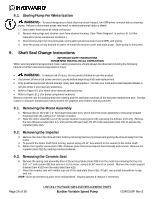
9.4. Seal Installation 8. Clean and lightly lubricate the motor shaft and seal recesses in the seal plate (item #15) with a dilute solution of non-granulated liquid-type soap. Gently wipe the polished face of the ceramic seal with a soft cotton cloth. Lubricate the rubber cup on the ceramic seat and press it firmly into the recess of the seal plate (item #15), with the polished ceramic surface facing out. 9. Reassemble the motor to the seal plate (item #15) using the four (4) 3/8" x 1" bolts (item #18), and re-attach the motor support (item #20) to the seal plate (item #15). 10. Gently wipe the black, polished surface of the spring seal assembly (item #13) with a soft cotton cloth. 11. Press the spring seal assembly (item #13) onto the motor shaft, with the black polished surface facing the ceramic seat. 9.5. Replacing the Impeller and Diffuser 12. Screw the impeller (item #12) onto the motor shaft in a clockwise direction, and screw the impeller screw (item #10) into the motor shaft in a counterclockwise direction. Tighten snugly by holding motor shaft with wrench as noted in step #4. Place the impeller ring (item #11) back onto the impeller (item #12), with flange facing towards the diffuser (item #9). 13. Place the diffuser (item #9) over the impeller (item #12) and onto the seal plate (item #15), aligning the three pins on the diffuser (item #9) with the three holes on the seal plate (item #15). Replace the two diffuser screws (item #7). 9.6. Replacing the Motor Assembly 14. Re-attach motor fan shroud (item #24) using the four (4) hex headed screws. Slide the motor assembly, with the diffuser (item #9) in place, into pump/strainer housing (item #3), being careful not to disturb the diffuser gasket (item #8). 15. Fasten assembly to pump/strainer housing (item #3) using the six (6) 5/16" x 2" bolts (item #17). (Be sure housing gasket (item #14) is in place, and lubricated. Replace if damaged). Tighten bolts alternately and evenly to 185 inch-pounds according to housing bolt torque pattern detail. Page 27 of 36 USE ONLY HAYWARD GENUINE REPLACEMENT PARTS EcoStar Variable Speed Pump IS3401VSP Rev-2
-
 1
1 -
2
-
3
-
4
-
5
-
6
-
7
-
8
-
9
-
10
-
11
-
12
-
13
-
14
-
15
-
16
-
17
-
18
-
19
-
20
-
21
-
 22
22 -
 23
23 -
 24
24 -
 25
25 -
 26
26 -
 27
27 -
 28
28 -
 29
29 -
 30
30 -
 31
31 -
 32
32 -
33
-
34
-
35
-
36
 |
 |
