Hayward Variable Speed Pump Owners Manual - Page 26
Shaft Seal Change Instructions - wiring diagram
 |
View all Hayward Variable Speed Pump manuals
Add to My Manuals
Save this manual to your list of manuals |
Page 26 highlights
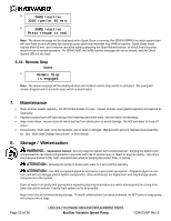
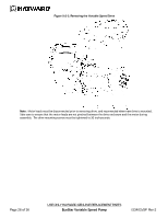
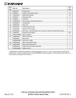
8.1. Storing Pump For Winterization WARNING - To avoid dangerous or fatal electrical shock hazard, turn OFF power to motor before draining pump. Failure to disconnect power may result in serious personal injury or death. 1. Drain water level below all inlets to the pool. 2. Remove drain plugs and strainer cover from strainer housing. (See "Parts Diagram" in section 10.1 of this manual for pump component locations.) 3. Disconnect pump from mounting pad, wiring (after power has been turned OFF), and piping. 4. Once the pump is fully drained of water, re-install the strainer cover and drain plugs. Store pump in a dry area. 9. Shaft Seal Change Instructions IMPORTANT SAFETY INSTRUCTIONS PLEASE READ AND FOLLOW ALL INSTRUCTIONS When servicing electrical equipment, basic safety precautions should always be observed including the following. Failure to follow instructions may result in injury. WARNING - To reduce risk of injury, do not permit children to use this product. Disconnect all electrical power service to pump before beginning shaft seal replacement. Only qualified personnel should attempt rotary seal replacement. Contact your local authorized Hayward Dealer or service center if you have any questions. Refer to Figure 9.6-1 for motor drive removal and mounting. Refer to Figure 10.1-1 for pump component locations. Exercise extreme care in handling both the rotating and the stationary sections of the two-part replacement seal. Foreign matter or improper handling will easily scratch the graphite and ceramic sealing surfaces. 9.1. Removing the Motor Assembly 1. Remove the six (6) 5/16" x 2" hex head bolts (item #17), which hold the motor assembly to the pump/strainer housing (item #3), using a 1/2" wrench or socket. 2. Slide the motor assembly out of the pump/strainer housing (item #3), exposing the diffuser (item #9). Remove the two diffuser screws (item #7), and pull the diffuser (item #9) off of the seal plate (item #15) to expose the impeller (item #12). 9.2. Removing the Impeller 3. Remove the motor fan shroud (item #24) by removing the four (4) screws and pulling the shroud away from the motor. 4. To prevent the motor shaft from turning, secure using a 5/16" hex wrench in the socket on the motor shaft. 5. Rotate the impeller screw (item #10) clockwise (note that screw has left-hand thread) and remove. Remove the impeller (item #12) by rotating counterclockwise. 9.3. Removing the Ceramic Seat 6. Remove the spring seal assembly (item #13) and seal plate (item #15) from the motor by removing the four (4) 3/8" x 1" bolts (item #18) that secure it to the motor, using a 9/16" wrench or socket. Remove the motor support bracket (item #20) from the seal plate (item #15). 7. Press the ceramic seat with rubber cup out of the seal plate (item #15). If tight, use a small screwdriver to tap seal out. STOP - Clean all recesses & parts to be reassembled. Inspect gaskets & replace if necessary. Page 26 of 36 USE ONLY HAYWARD GENUINE REPLACEMENT PARTS EcoStar Variable Speed Pump IS3401VSP Rev-2
-
 1
1 -
2
-
3
-
4
-
5
-
6
-
7
-
8
-
9
-
10
-
11
-
12
-
13
-
14
-
15
-
16
-
17
-
18
-
19
-
20
-
 21
21 -
 22
22 -
 23
23 -
 24
24 -
 25
25 -
 26
26 -
 27
27 -
 28
28 -
 29
29 -
 30
30 -
 31
31 -
32
-
33
-
34
-
35
-
36
 |
 |