Hayward Variable Speed Pump Owners Manual - Page 14
Wiring Diagrams - reviews
 |
View all Hayward Variable Speed Pump manuals
Add to My Manuals
Save this manual to your list of manuals |
Page 14 highlights
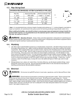
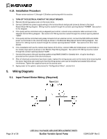
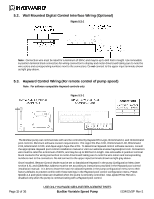
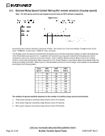
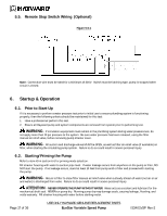
4.14. Installation Procedure Please review sections 4.1 through 4.13 before continuing with this section. 1. TURN OFF THE ELECTRICAL POWER AT THE CIRCUIT BREAKER. 2. Remove the wiring access cover on the motor drive. 3. Connect 230VAC line power supply wiring to the terminal block and ground screw as shown in the Input Power/Motor Wiring diagram. Wiring must be routed through the conduit opening labeled "POWER". See section 5.1 for diagram. 4. If the pump will be controlled using a Hayward pool control, connect a two-conductor cable as shown in the Hayward Control Wiring diagram. See section 5.3. Wiring must be routed through the conduit opening labeled "DATA". 5. If the pump will be controlled using relay contacts from an external control, connect the INP1-INP3 and 12VAC power out terminals to the external relays as shown in the External Relay Speed Control Wiring diagram. See section 5.4. Wiring must be routed through the conduit opening labeled "DATA". See section 6.6.11 for more details. 6. If the installation will use the remote stop feature of the drive, connect INP4 and 12VAC power out terminals to the remote stop switch as shown in the Remote Stop Wiring diagram. See section 5.5. Wiring must be routed through the conduit opening labeled "DATA". 7. Connect the pump to the pool bonding system using 8AWG (6AWG for Canada) wire. A lug for bonding is provided on the outside of the drive enclosure. 8. After all electrical connections have been made, replace the wiring access cover on the motor drive ensuring that the motor lead wires are routed such that the wiring access cover can be installed and seated fully without interference. Tighten the supplied screw on the access cover. 9. Apply power to the system, and proceed to "Configuration Menu", section 6.6. 5. Wiring Diagrams 5.1. Input Power/Motor Wiring (Required) Figure 5.1-1 Page 14 of 36 USE ONLY HAYWARD GENUINE REPLACEMENT PARTS EcoStar Variable Speed Pump IS3401VSP Rev-2
-
 1
1 -
2
-
3
-
4
-
5
-
6
-
7
-
8
-
 9
9 -
 10
10 -
 11
11 -
 12
12 -
 13
13 -
 14
14 -
 15
15 -
 16
16 -
 17
17 -
 18
18 -
 19
19 -
20
-
21
-
22
-
23
-
24
-
25
-
26
-
27
-
28
-
29
-
30
-
31
-
32
-
33
-
34
-
35
-
36
 |
 |