Hayward Variable Speed Pump Owners Manual - Page 12
Digital Control Interface Orientation, Interface Wall Mounting - drives
 |
View all Hayward Variable Speed Pump manuals
Add to My Manuals
Save this manual to your list of manuals |
Page 12 highlights
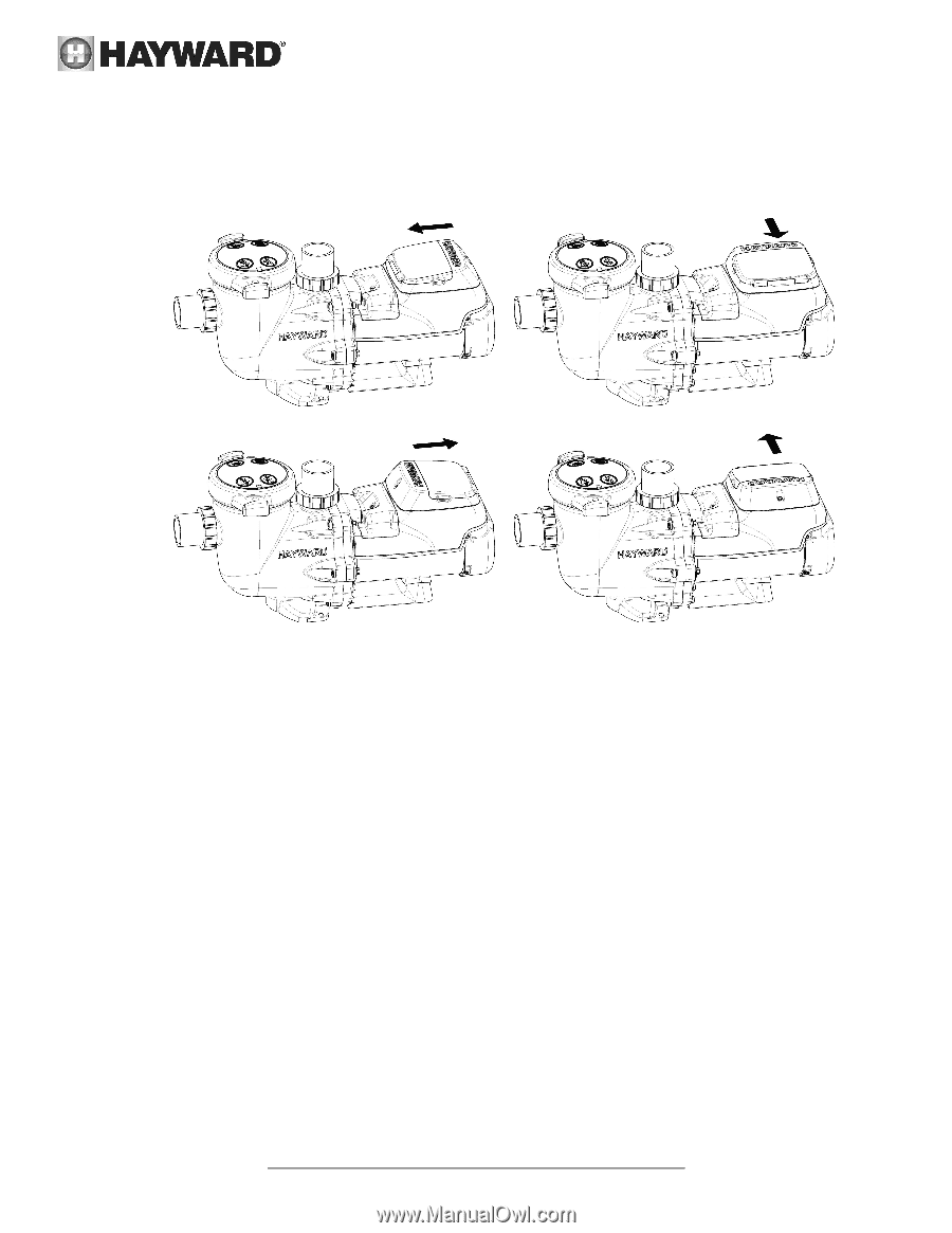
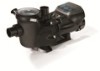
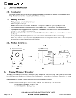
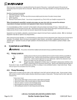
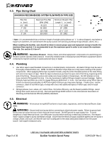
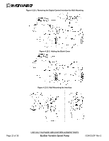
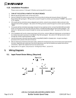
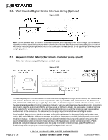
4.12. Digital Control Interface Orientation The Digital Control Interface can be rotated to any of four desired positions after installation by removing the two screws securing the interface to the motor drive, lifting the interface and rotating it to the desired position, and replacing the two screws in the new position. (Figure 4.12-1) Figure 4.12-1 4.13. Interface Wall Mounting The interface can also be wall mounted using the parts supplied in the wall mount kit using the following procedure. 1. TURN OFF THE ELECTRICAL POWER AT THE CIRCUIT BREAKER. 2. Remove the two screws securing the interface to the motor drive. (Figure 4.13-1) 3. Disconnect the short cable that extends out from the motor drive. (Figure 4.13-1) 4. Install the blank cover, SP3200DR9, on the motor drive in the desired orientation. This cover is important to protect internal electronics. (Figure 4.13-2) 5. Mount the wall mount plate, SP3200DR10, in the desired location. (Figure 4.13-3) 6. Connect the interface cable as shown in the Wall Mounted Digital Control Interface Wiring diagram shown in section 5.2 to the motor drive and interface PCB. The cable must be routed through the "DATA" conduit opening on the motor drive and through the slot provided on the backside of the wall mount plate, SP3200DR10. Cable used may be up to 500 feet in length. (Figure 4.13-3) 7. Mount the interface to the wall mount plate, SP3200DR10, using the two screws. (Figure 4.13-3) 8. Apply power to the system and resume normal operation. The following diagrams on the next page help illustrate the interface wall mounting procedure. Page 12 of 36 USE ONLY HAYWARD GENUINE REPLACEMENT PARTS EcoStar Variable Speed Pump IS3401VSP Rev-2
-
 1
1 -
2
-
3
-
4
-
5
-
6
-
 7
7 -
 8
8 -
 9
9 -
 10
10 -
 11
11 -
 12
12 -
 13
13 -
 14
14 -
 15
15 -
 16
16 -
 17
17 -
18
-
19
-
20
-
21
-
22
-
23
-
24
-
25
-
26
-
27
-
28
-
29
-
30
-
31
-
32
-
33
-
34
-
35
-
36
 |
 |