HP BladeSystem bc2800 HP BladeSystem PC Blade Switch Installation Guide - Page 7
Introduction, Switch Management - blade pc
 |
View all HP BladeSystem bc2800 manuals
Add to My Manuals
Save this manual to your list of manuals |
Page 7 highlights
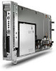
1 Introduction The Consolidated Client Infrastructure (CCI) solution uses a 3U (5.25-inch) HP BladeSystem PC Blade Enclosure supporting 20 HP Blade PCs and redundant, hot-plug power and cooling. The HP BladeSystem PC Blade enclosure with 20 HP blade PCs contains 40 10/100 Mbps network adapters (NIC). Since the CCI solution packages many HP Blade PCs in a small space, the number of network cables within this space can quickly become overwhelming. The HP PC Blade enclosure includes a slot for an interconnect switch used to provide external Ethernet connectivity. The HP PC Blade Switch can provide up to a 41-to-1 reduction in network cables. This cable reduction significantly reduces the time required to deploy, manage, and service the CCI solution. This Installation Guide describes the HP PC Blade Switch configuration and is intended for applications that require 100 megabit per second (Mbps) Fast Ethernet NIC aggregation to 10/100/1000 megabits per second (Mbps) copper or 1000 Mbps Fiber Ethernet uplinks. Switch Management The HP BladeSystem PC Blade Switch is an industry-standard managed layer 2+ Ethernet switch that can be configured and manage the switch like any other industry-standard Ethernet switch. A browser-based interface and a command line interface (CLI) are embedded in the switch firmware to configure, manage, and monitor the switch. The switch also supports Telnet access, Secure Shell (SSH) support, Simple Network Management Protocol (SNMP) v1-v3, and Remote Monitoring (RMON). Any internal or external ports can be disabled, enabled, configured, or monitored on a per port basis. Dedicated access to the switch management interface is supported locally using the Integrated Administrator or remotely through any configured virtual LAN (VLAN) management interface. ENWW Switch Management 1
-
 1
1 -
 2
2 -
 3
3 -
 4
4 -
 5
5 -
 6
6 -
 7
7 -
 8
8 -
 9
9 -
 10
10 -
 11
11 -
 12
12 -
13
-
14
-
15
-
16
-
17
-
18
-
19
-
20
-
21
-
22
-
23
-
24
-
25
-
26
-
27
-
28
-
29
-
30
-
31
-
32
-
33
-
34
-
35
-
36
-
37
-
38
-
39
 |
 |