HP Color LaserJet Enterprise CP4020 Service Manual - Page 428
Table 3-20, Causes and solutions for residual media jams
 |
View all HP Color LaserJet Enterprise CP4020 manuals
Add to My Manuals
Save this manual to your list of manuals |
Page 428 highlights
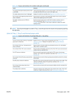
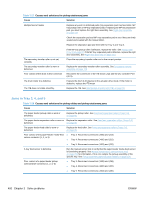
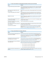
Table 3-20 Causes and solutions for residual media jams Cause Solution The sensor detecting a residual media jam is not working. One of the four sensors is reporting a residual jam. Test each sensor using the manual sensor test. See Manual sensor test (special-mode test) on page 246 for information. If the sensor does not respond, replace the component indicated: ● TOP sensor (SR20): Replace the registration assembly. See Registration assembly on page 128. ● Fuser delivery sensor (SR5): Replace the sensor. See callout 3 in Figure 2-114 Remove the delivery assembly (2 of 7) on page 146 for the sensor location. ● Loop sensor 1 or 2 (SR14 and SR15): Replace the fuser. See Fuser on page 85. ● Duplex re-pickup sensor (SR22): Replace the registration assembly. See Registration assembly on page 128. If service was recently performed on the product, a sensor connector might be disconnected. Run the manual sensor tests to verify which sensor detects the media. See Manual sensor test (special-mode test) on page 246 for information. Reconnect the corresponding sensor connector: ● TOP sensor: Connector (J74) and (J145) on the DC controller PCA ● Fuser delivery sensor: Connector (J48) and connector (J127) on the DC controller PCA ● Loop sensor 1 or 2: Connector (J162) on the DC controller PCA ● Duplex re-pickup sensor: Intermediate connector (J74) and connector (J145) on the DC controller PCA. Table 3-21 Causes and solutions for pickup delay jams 2 Cause Solution Poor contact of the pickup motor drive connector. Reconnect the connector (J37) of the pickup motor and connector (J260) of the DC controller PCA . The pickup motor is defective. Execute the pickup-motor driving test in the actuator-drive mode. If the motor is defective, replace the pickup motor. See Pickup motor on page 172. The pickup roller is worn or deformed. Replace the pickup roller. See Feed and separation rollers (Trays 2-5) on page 86. The tray 2 separation roller is worn or deformed. Replace the separation roller. See Feed and separation rollers (Trays 2-5) on page 86. Poor contact of the TOP sensor connector. Reconnect the intermediate connector (J74) of the TOP sensor and connector (J145) on the DC controller PCA. The TOP sensor (SR20) is defective. Run the manual sensor test to verify that the TOP sensor is functioning properly. See Manual sensor test (special-mode test) on page 246 for information. If it is not, replace the registration assembly. See Registration assembly on page 128. Poor contact of the pickup solenoid drive connector. Reconnect the connector (J59) of the pickup solenoid and (J115) on the DC controller PCA. 396 Chapter 3 Solve problems ENWW
-
 1
1 -
2
-
3
-
4
-
5
-
6
-
7
-
8
-
9
-
10
-
11
-
12
-
13
-
14
-
15
-
16
-
17
-
18
-
19
-
20
-
21
-
22
-
23
-
24
-
25
-
26
-
27
-
28
-
29
-
30
-
31
-
32
-
33
-
34
-
35
-
36
-
37
-
38
-
39
-
40
-
41
-
42
-
43
-
44
-
45
-
46
-
47
-
48
-
49
-
50
-
51
-
52
-
53
-
54
-
55
-
56
-
57
-
58
-
59
-
60
-
61
-
62
-
63
-
64
-
65
-
66
-
67
-
68
-
69
-
70
-
71
-
72
-
73
-
74
-
75
-
76
-
77
-
78
-
79
-
80
-
81
-
82
-
83
-
84
-
85
-
86
-
87
-
88
-
89
-
90
-
91
-
92
-
93
-
94
-
95
-
96
-
97
-
98
-
99
-
100
-
101
-
102
-
103
-
104
-
105
-
106
-
107
-
108
-
109
-
110
-
111
-
112
-
113
-
114
-
115
-
116
-
117
-
118
-
119
-
120
-
121
-
122
-
123
-
124
-
125
-
126
-
127
-
128
-
129
-
130
-
131
-
132
-
133
-
134
-
135
-
136
-
137
-
138
-
139
-
140
-
141
-
142
-
143
-
144
-
145
-
146
-
147
-
148
-
149
-
150
-
151
-
152
-
153
-
154
-
155
-
156
-
157
-
158
-
159
-
160
-
161
-
162
-
163
-
164
-
165
-
166
-
167
-
168
-
169
-
170
-
171
-
172
-
173
-
174
-
175
-
176
-
177
-
178
-
179
-
180
-
181
-
182
-
183
-
184
-
185
-
186
-
187
-
188
-
189
-
190
-
191
-
192
-
193
-
194
-
195
-
196
-
197
-
198
-
199
-
200
-
201
-
202
-
203
-
204
-
205
-
206
-
207
-
208
-
209
-
210
-
211
-
212
-
213
-
214
-
215
-
216
-
217
-
218
-
219
-
220
-
221
-
222
-
223
-
224
-
225
-
226
-
227
-
228
-
229
-
230
-
231
-
232
-
233
-
234
-
235
-
236
-
237
-
238
-
239
-
240
-
241
-
242
-
243
-
244
-
245
-
246
-
247
-
248
-
249
-
250
-
251
-
252
-
253
-
254
-
255
-
256
-
257
-
258
-
259
-
260
-
261
-
262
-
263
-
264
-
265
-
266
-
267
-
268
-
269
-
270
-
271
-
272
-
273
-
274
-
275
-
276
-
277
-
278
-
279
-
280
-
281
-
282
-
283
-
284
-
285
-
286
-
287
-
288
-
289
-
290
-
291
-
292
-
293
-
294
-
295
-
296
-
297
-
298
-
299
-
300
-
301
-
302
-
303
-
304
-
305
-
306
-
307
-
308
-
309
-
310
-
311
-
312
-
313
-
314
-
315
-
316
-
317
-
318
-
319
-
320
-
321
-
322
-
323
-
324
-
325
-
326
-
327
-
328
-
329
-
330
-
331
-
332
-
333
-
334
-
335
-
336
-
337
-
338
-
339
-
340
-
341
-
342
-
343
-
344
-
345
-
346
-
347
-
348
-
349
-
350
-
351
-
352
-
353
-
354
-
355
-
356
-
357
-
358
-
359
-
360
-
361
-
362
-
363
-
364
-
365
-
366
-
367
-
368
-
369
-
370
-
371
-
372
-
373
-
374
-
375
-
376
-
377
-
378
-
379
-
380
-
381
-
382
-
383
-
384
-
385
-
386
-
387
-
388
-
389
-
390
-
391
-
392
-
393
-
394
-
395
-
396
-
397
-
398
-
399
-
400
-
401
-
402
-
403
-
404
-
405
-
406
-
407
-
408
-
409
-
410
-
411
-
412
-
413
-
414
-
415
-
416
-
417
-
418
-
419
-
420
-
421
-
422
-
 423
423 -
 424
424 -
 425
425 -
 426
426 -
 427
427 -
 428
428 -
 429
429 -
 430
430 -
 431
431 -
 432
432 -
 433
433 -
434
-
435
-
436
-
437
-
438
-
439
-
440
-
441
-
442
-
443
-
444
-
445
-
446
-
447
-
448
-
449
-
450
-
451
-
452
-
453
-
454
-
455
-
456
-
457
-
458
-
459
-
460
-
461
-
462
-
463
-
464
-
465
-
466
-
467
-
468
-
469
-
470
-
471
-
472
-
473
-
474
-
475
-
476
-
477
-
478
-
479
-
480
-
481
-
482
-
483
-
484
-
485
-
486
-
487
-
488
-
489
-
490
-
491
-
492
-
493
-
494
-
495
-
496
-
497
-
498
-
499
-
500
-
501
-
502
-
503
-
504
-
505
-
506
-
507
-
508
-
509
-
510
-
511
-
512
-
513
-
514
-
515
-
516
-
517
-
518
-
519
-
520
-
521
-
522
-
523
-
524
-
525
-
526
-
527
-
528
-
529
-
530
-
531
-
532
-
533
-
534
-
535
-
536
-
537
-
538
-
539
-
540
-
541
-
542
-
543
-
544
-
545
-
546
-
547
-
548
-
549
-
550
-
551
-
552
-
553
-
554
-
555
-
556
-
557
-
558
 |
 |
