| Section |
Page |
| Theory of operation |
33 |
| Basic operation |
34 |
| Sequence of operation |
35 |
| Engine-control system |
36 |
| DC controller |
37 |
| Solenoids |
37 |
| Clutches |
38 |
| Switches |
38 |
| Sensors |
39 |
| Motors |
40 |
| Fans |
41 |
| High-voltage power supply |
42 |
| Low-voltage power supply |
44 |
| Overcurrent/overvoltage protection |
45 |
| Safety |
45 |
| Voltage detection |
45 |
| Sleep (powersave) mode |
45 |
| Low-voltage power supply failure |
45 |
| Fuser control |
46 |
| Fuser temperature control |
47 |
| Fuser sleeve temperature protection |
47 |
| Failure detection |
48 |
| Fuser unit identification |
49 |
| Fuser unit life detection |
49 |
| Laser/scanner system |
50 |
| Laser/scanner failure |
51 |
| Protective-glass cleaners |
51 |
| Image-formation system |
53 |
| Image-formation process |
55 |
| Step 1: Pre-exposure |
56 |
| Step 2: Primary charging |
56 |
| Step 3: Laser-beam exposure |
57 |
| Step 4: Development |
57 |
| Step 5: Primary transfer |
58 |
| Step 6: Secondary transfer |
58 |
| Step 7: Separation |
59 |
| Step 8: Fusing |
59 |
| Step 9: ITB cleaning |
60 |
| Step 10: Drum cleaning |
60 |
| Print cartridge |
60 |
| Developing-roller engagement and disengagement |
62 |
| Intermediate transfer belt (ITB) unit |
63 |
| Primary-transfer-roller engagement and disengagement |
64 |
| ITB cleaning |
66 |
| Calibration |
66 |
| Color-misregistration control |
67 |
| Image-stabilization control |
67 |
| Pickup, feed, and delivery system |
69 |
| Pickup-and-feed unit |
73 |
| Cassette pickup |
73 |
| Cassette-presence detection |
74 |
| Cassette lift operation and cassette paper-presence detection |
75 |
| Cassette multiple-feed prevention |
75 |
| Multipurpose tray pickup |
76 |
| Paper feed |
77 |
| Skew-feed prevention |
79 |
| Paper detection |
79 |
| Feed speed control |
80 |
| Fusing and delivery unit |
80 |
| Loop control |
81 |
| Pressure-roller pressurization control |
83 |
| Duplexing unit (HP Color LaserJet CP4525dn, HP Color LaserJet CP4025dn, and HP Color LaserJet CP4525 ... |
84 |
| Duplexing reverse and feed control |
84 |
| Duplex print operation |
85 |
| Jam detection |
87 |
| Optional paper feeder |
89 |
| Motor control |
91 |
| Paper-feeder pickup and feed operation |
92 |
| Paper-size detection and cassette-presence detection |
94 |
| Paper-feeder cassette lift operation |
95 |
| Paper feeder jam detection |
96 |
| Removal and replacement |
99 |
| Introduction |
100 |
| Removal and replacement strategy |
100 |
| Electrostatic discharge |
101 |
| Required tools |
101 |
| Before performing service |
102 |
| After performing service |
102 |
| Post-service test |
103 |
| Print-quality test |
103 |
| Parts removal order |
104 |
| Customer self repair (CSR) components |
106 |
| Print cartridges |
106 |
| Toner-collection unit |
108 |
| Formatter PCA |
110 |
| Hard drive |
111 |
| Remove the hard drive |
111 |
| Memory DIMM |
113 |
| Remove the memory DIMM |
113 |
| Enable memory |
114 |
| Tray |
116 |
| Fuser |
117 |
| Feed and separation rollers (Trays 2-5) |
118 |
| Pickup roller (Tray 1) |
119 |
| Secondary transfer roller |
122 |
| Reinstall the transfer roller |
123 |
| Intermediate transfer belt (ITB) |
124 |
| External panels, covers, and doors |
127 |
| Identification and location |
127 |
| Upper-left cover |
128 |
| Power-supply cover |
130 |
| Left cover |
131 |
| Remove the left cover |
131 |
| Front-top cover |
132 |
| Remove the front-top cover |
132 |
| Rear-top cover |
134 |
| Remove the rear-top cover |
134 |
| Right-front cover |
135 |
| Remove the right-front cover |
135 |
| Reinstall the power button |
136 |
| Control-panel assembly |
137 |
| Remove the control-panel assembly |
137 |
| Front-door assembly |
139 |
| Remove the front-door assembly |
139 |
| Right-rear cover |
142 |
| Remove the right-rear cover |
142 |
| Rear cover |
144 |
| Remove the rear cover |
144 |
| Right-door assembly |
145 |
| Internal assemblies |
150 |
| Cassette feed guide |
150 |
| Secondary transfer assembly |
151 |
| Reinstall the secondary transfer assembly |
152 |
| Separation pad (Tray 1) |
153 |
| Remove the separation pad (Tray 1) |
153 |
| Registration density (RD) sensor assembly |
156 |
| Remove the RD sensor assembly |
156 |
| Registration assembly |
160 |
| Remove the registration assembly |
161 |
| Residual-toner-feed motor |
165 |
| Remove the residual-toner-feed motor |
165 |
| Residual-toner duct and feed assembly |
166 |
| Remove the residual-toner duct and feed assembly |
166 |
| Cartridge fan and environmental sensor |
169 |
| Remove the cartridge fan and environmental sensor |
169 |
| Toner-collection sensor and scanner-thermistor assembly |
173 |
| Remove the toner-collection sensor and scanner-thermistor assembly |
173 |
| Delivery fan |
175 |
| Remove the delivery fan |
175 |
| Delivery assembly |
177 |
| Remove the delivery assembly |
177 |
| Reinstall the delivery assembly |
181 |
| Duplex-drive assembly |
183 |
| Remove the duplex-drive assembly |
183 |
| Power-supply fan |
184 |
| Remove the power-supply fan |
184 |
| Interconnect board (ICB) |
185 |
| Remove the ICB |
185 |
| DC controller PCA only |
187 |
| Remove the DC controller PCA only |
187 |
| Low-voltage power supply (LVPS) |
189 |
| Remove the low-voltage power supply |
189 |
| DC controller PCA and tray |
193 |
| Remove the DC controller PCA and tray |
193 |
| High-voltage power supply lower (HVPS-D) |
195 |
| Remove the high-voltage power supply lower |
195 |
| Reinstall the high-voltage power supply lower |
199 |
| Developing-disengagement motor |
200 |
| Remove the developing-disengagement motor |
200 |
| Exhaust fan and fan duct |
201 |
| Remove the exhaust fan and fan duct |
201 |
| Reinstall the exhaust fan and fan duct |
203 |
| Pickup motor |
204 |
| Remove the pickup motor |
204 |
| Lifter-drive assembly |
205 |
| Remove the lifter-drive assembly |
205 |
| Lifter base assembly |
207 |
| Remove the lifter base assembly |
207 |
| Reinstall the lifter base assembly |
208 |
| Tray-pickup drive assembly |
210 |
| Remove the tray-pickup drive assembly |
210 |
| Tray-pickup assembly |
212 |
| Remove the tray-pickup assembly |
212 |
| Laser/scanner assembly (Y/M) |
218 |
| Remove the laser/scanner assembly (Y/M) |
219 |
| Laser/scanner assembly (C/Bk) |
222 |
| Remove the laser/scanner assembly (C/Bk) |
223 |
| Reinstall the protective glass cleaner (PGC) actuators |
225 |
| High-voltage power supply upper (HVPS-T) |
228 |
| Remove the high-voltage power supply upper |
228 |
| Reinstall the high-voltage power supply upper |
230 |
| Yellow, magenta, cyan, and black drum motors |
231 |
| Remove the yellow, magenta, cyan, and black drum motors |
231 |
| Fuser motor |
232 |
| Remove the fuser motor |
233 |
| ITB motor |
234 |
| Remove the ITB motor |
234 |
| Main-drive assembly |
235 |
| Remove the main-drive assembly |
236 |
| Reinstall the main-drive assembly |
239 |
| Fuser-drive assembly |
243 |
| Remove the fuser-drive assembly |
244 |
| Reinstall the fuser-drive assembly |
247 |
| Optional paper feeder assemblies (1 x 500-sheet and 3 x 500-sheet) |
248 |
| Front door (optional paper feeder) |
248 |
| Rear cover (optional paper feeder) |
250 |
| Right-front cover (optional paper feeder) |
251 |
| Right door (optional paper feeder) |
252 |
| Left cover (optional paper feeder) |
254 |
| Remove the left cover (optional paper feeder) |
254 |
| Right cover (optional paper feeder) |
256 |
| Remove the right cover (optional paper feeder) |
256 |
| Rear-right cover (optional paper feeder) |
257 |
| Remove the rear-right cover (optional paper feeder) |
257 |
| Pickup assembly (optional paper feeder) |
258 |
| Remove the pickup assembly (optional paper feeder) |
258 |
| Lifter assembly (optional paper feeder) |
261 |
| Remove the lifter assembly (optional paper feeder) |
261 |
| Lifter-drive assembly (optional paper feeder) |
262 |
| Remove the lifter-drive assembly (optional paper feeder) |
262 |
| Pickup motor assembly (optional paper feeder) |
263 |
| Remove the pickup motor (optional paper feeder) assembly |
263 |
| Controller PCA (optional paper feeder) |
264 |
| Remove the controller PCA (optional paper feeder) |
264 |
| Solve problems |
265 |
| Solve problems checklist |
266 |
| Menu map |
268 |
| Troubleshooting process |
269 |
| Determine the problem source |
269 |
| Pre-troubleshooting checklist |
269 |
| Troubleshooting flowchart |
271 |
| Power subsystem |
272 |
| Power-on checks |
272 |
| Power-on troubleshooting overview |
272 |
| Tools for troubleshooting |
274 |
| Individual component diagnostics |
274 |
| LED diagnostics |
274 |
| Understand lights on the formatter |
274 |
| HP Jetdirect LEDs |
274 |
| Heartbeat LED |
275 |
| Engine diagnostics |
275 |
| Defeating interlocks |
275 |
| Disable cartridge check |
276 |
| Engine-test button |
276 |
| Paper-path test |
277 |
| Manual sensor test (special-mode test) |
278 |
| A TOP (top of page) sensor |
279 |
| B and C loop sensors |
280 |
| D fuser delivery sensor |
281 |
| E duplex re-pickup sensor |
282 |
| F output bin full sensor |
283 |
| I developer alienation |
284 |
| J fuser pressure-release sensor |
285 |
| K primary transfer-roller-disengagement sensor |
286 |
| L media sensor |
288 |
| M front-door switch |
289 |
| N right-door switch |
290 |
| Manual sensor test 2 (special-mode test) |
291 |
| O Tray 1 paper present sensor |
293 |
| P Tray 2 paper present sensor |
294 |
| Q Tray 2 paper surface 1 and 2 sensors |
295 |
| R Tray 2 paper size switches |
296 |
| S Tray 3 paper present sensor |
297 |
| T Tray 3 feed sensor |
297 |
| U Tray 3 paper surface 1 and 2 sensors |
297 |
| V Tray 3 paper size switches |
297 |
| W Tray 4 paper present sensor |
297 |
| X Tray 4 feed sensor |
297 |
| Y Tray 4 paper surface 1 and 2 sensors |
297 |
| Z Tray 4 paper size switches |
298 |
| a Tray 5 paper present sensor |
298 |
| b Tray 5 feed sensor |
298 |
| c Tray 5 paper surface 1 and 2 sensors |
298 |
| d Tray 5 paper size switches |
298 |
| 5V laser and 24V interlock and logic switches (and power switch) |
299 |
| Location and testing |
299 |
| Defeating |
300 |
| New ITB sensor |
303 |
| Tray 3, 4, and 5 right door switch |
304 |
| Paper-path sensors test |
305 |
| Print/stop test |
305 |
| Component tests |
306 |
| Component test (special-mode test) |
306 |
| Diagrams |
309 |
| Block diagrams |
309 |
| Plug/jack locations |
312 |
| Location of connectors |
313 |
| DC controller connector locations |
313 |
| Controller PCA (1 x 500-sheet and 3 x 500-sheet optional paper feeders) |
315 |
| Locations of major components |
316 |
| General timing chart |
326 |
| Circuit diagrams |
327 |
| HP Easy Printer Care |
331 |
| Open the HP Easy Printer Care software |
331 |
| HP Easy Printer Care software sections |
331 |
| Internal print-quality test pages |
334 |
| Print-quality-troubleshooting pages |
334 |
| Diagnostics page |
337 |
| Cleaning page |
338 |
| Configuration page |
339 |
| Configuration page |
339 |
| HP embedded Jetdirect page |
341 |
| Embedded protocol page |
342 |
| Finding important information on the configuration pages |
343 |
| Color-band test |
343 |
| Print-quality troubleshooting tools |
344 |
| Repetitive defects ruler |
344 |
| Calibrate the product |
345 |
| Control panel menus |
346 |
| Control panel menus |
346 |
| Show Me How menu |
346 |
| Retrieve job menu |
346 |
| Information menu |
349 |
| Paper handling menu |
349 |
| Manage supplies menu |
350 |
| Configure device menu |
353 |
| Printing menu |
353 |
| PCL sub-menu |
355 |
| Print Quality menu |
356 |
| System setup menu |
361 |
| I/O menu |
366 |
| Resets menu |
374 |
| Diagnostics menu |
374 |
| Service menu |
376 |
| Interpret control-panel messages |
377 |
| Control-panel message types |
377 |
| Control-panel messages |
377 |
| Event log messages |
408 |
| Print an event log |
408 |
| Show an event log |
408 |
| Sample event log |
409 |
| Clear the event log |
409 |
| Event log message table |
410 |
| Clear paper jams |
415 |
| Common causes of jams |
415 |
| Jam locations |
418 |
| Clear jams in the right door |
419 |
| Clear jams in the output bin area |
422 |
| Clear jams in Tray 1 |
422 |
| Clear jams in Tray 2 or optional Trays 3, 4, or 5 |
424 |
| Clear jams in the lower right door (Tray 3, 4, or 5) |
425 |
| Jam causes and solutions |
426 |
| Jams in the output bin |
426 |
| Jams in the fuser and transfer area |
426 |
| Jams in the duplex area (HP Color LaserJet CP4525dn, HP Color LaserJet CP4025dn, and HP Color LaserJ ... |
429 |
| Jams in Tray 1, Tray 2 and internal paper path |
431 |
| Jams in Tray 3, 4, and 5 |
432 |
| Change jam recovery |
434 |
| Solve paper-handling problems |
435 |
| Product feeds multiple sheets |
435 |
| Product feeds incorrect page size |
435 |
| Product pulls from incorrect tray |
435 |
| Paper does not feed automatically |
436 |
| Paper does not feed from Tray 2, 3, 4, or 5 |
436 |
| Transparencies or glossy paper will not feed |
437 |
| Envelopes jam or will not feed in the product |
437 |
| Output is curled or wrinkled |
438 |
| Product will not duplex or duplexes incorrectly |
438 |
| Use manual print modes |
440 |
| Solve image-quality problems |
442 |
| Image defects table |
442 |
| Clean the product |
448 |
| Clean the paper path |
448 |
| Solve performance problems |
449 |
| Solve connectivity problems |
450 |
| Solve direct-connect problems |
450 |
| Solve network problems |
450 |
| Service mode functions |
452 |
| Service menu |
452 |
| Product resets |
455 |
| Restore factory-set defaults |
455 |
| Hard disk initialization (optional) |
455 |
| NVRAM initialization |
455 |
| Product cold reset |
456 |
| Product updates |
456 |
| Parts and diagrams |
457 |
| Order parts, accessories, and supplies |
458 |
| Part numbers |
459 |
| Accessories |
459 |
| Print cartridges and toner collection unit |
459 |
| Memory |
459 |
| Cables and interfaces |
459 |
| Customer self repair (CSR) parts |
460 |
| Service maintenance kits |
460 |
| Unique components |
461 |
| Screws |
462 |
| How to use the parts lists and diagrams |
463 |
| External covers, panels, and doors |
464 |
| Right door assembly |
466 |
| Front door assembly |
468 |
| Internal components |
470 |
| Internal components (1 of 7) |
470 |
| Internal components (2 of 7) |
472 |
| Internal components (3 of 7) |
474 |
| Internal components (4 of 7) |
476 |
| Internal components (5 of 7) |
478 |
| Internal components (6 of 7) |
480 |
| Internal components (7 of 7) |
482 |
| Cassettes 2-5 |
484 |
| Paper pickup assembly |
486 |
| Tray 1 paper pickup assembly |
488 |
| Registration assembly |
490 |
| Secondary transfer assembly |
492 |
| Delivery assembly |
494 |
| Fuser assembly |
496 |
| PCAs |
498 |
| Assessories |
500 |
| Paper feeders |
500 |
| Paper feeder external covers, panels, and doors |
502 |
| 1 X 500 paper feeder main body |
504 |
| 3 X 500 paper feeder main body |
506 |
| Alphabetical parts list |
508 |
| Numerical parts list |
516 |
| Service and support |
525 |
| Hewlett-Packard limited warranty statement |
526 |
| HP's Premium Protection Warranty: LaserJet print cartridge limited warranty statement |
527 |
| HP Color LaserJet Fuser Kit Limited Warranty Statement |
528 |
| End User License Agreement |
529 |
| Customer self-repair warranty service |
531 |
| Customer support |
532 |
| Product specifications |
533 |
| Physical specifications |
534 |
| Performance specifications |
534 |
| Electrical specifications |
534 |
| Acoustic specifications |
535 |
| Environmental specifications |
535 |
| Skew specifications |
536 |
| Regulatory information |
537 |
| FCC regulations |
538 |
| Environmental product stewardship program |
539 |
| Protecting the environment |
539 |
| Ozone production |
539 |
| Power consumption |
539 |
| Toner consumption |
539 |
| Paper use |
539 |
| Plastics |
539 |
| HP LaserJet print supplies |
539 |
| Return and recycling instructions |
540 |
| United States and Puerto Rico |
540 |
| Multiple returns (more than one cartridge) |
540 |
| Single returns |
540 |
| Shipping |
540 |
| Residents of Alaska and Hawaii |
540 |
| Non-U.S. returns |
540 |
| Paper |
540 |
| Material restrictions |
541 |
| Disposal of waste equipment by users in private households in the European Union |
541 |
| Chemical substances |
541 |
| Material Safety Data Sheet (MSDS) |
542 |
| For more information |
542 |
| Declaration of Conformity |
543 |
| Safety statements |
544 |
| Laser safety |
544 |
| Canadian DOC regulations |
544 |
| VCCI statement (Japan) |
544 |
| Power cord instructions |
544 |
| Power cord statement (Japan) |
544 |
| EMC statement (China) |
545 |
| EMC statement (Korea) |
545 |
| EMI statement (Taiwan) |
545 |
| Laser statement for Finland |
545 |
| GS statement (Germany) |
546 |
| Substances Table (China) |
546 |
| Restriction on Hazardous Substances statement (Turkey) |
546 |
 1
1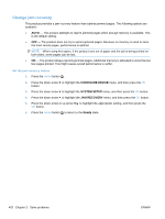 434
434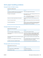 435
435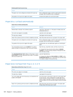 436
436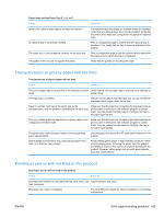 437
437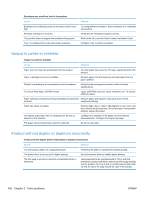 438
438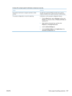 439
439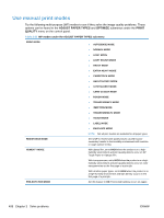 440
440 441
441 442
442 443
443 444
444

