HP ENVY 15-ar000 Maintenance and Service Guide - Page 43
Fan/heat sink assembly, that secure the fan/heat sink assembly
 |
View all HP ENVY 15-ar000 manuals
Add to My Manuals
Save this manual to your list of manuals |
Page 43 highlights
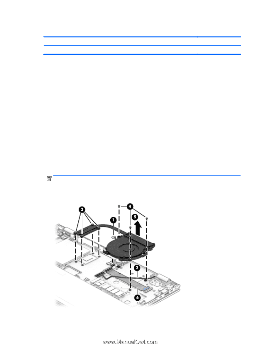
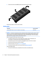
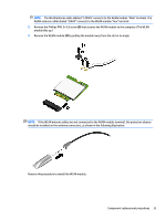
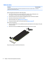
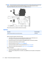
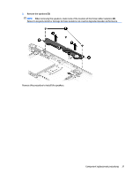
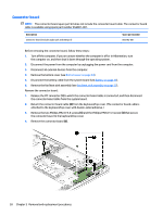
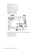
Fan/heat sink assembly Description Fan/heat sink assembly (includes replacement thermal material) Spare part number 856306-001 Before removing the fan/heat sink assembly, follow these steps: 1. Turn off the computer. If you are unsure whether the computer is off or in Hibernation, turn the computer on, and then shut it down through the operating system. 2. Disconnect the power from the computer by unplugging the power cord from the computer. 3. Disconnect all external devices from the computer. 4. Remove the bottom cover (see Bottom cover on page 24). 5. Disconnect the battery cable from the system board (see Battery on page 26). Remove the fan/heat sink assembly: 1. Disconnect the fan cable (1) from the system board. 2. Release the display panel cable (2) from the retention clips and channel built into the fan. 3. Loosen the four Phillips PM2.0×6.2 captive screws (3) that secure the fan/heat sink assembly to the system board. 4. Remove the three Phillips PM2.0×4.6 screws (4) that secure the fan to the keyboard/top cover. 5. Remove the fan/heat sink assembly (5). NOTE: It is necessary to detach the fan/heat sink assembly from the connector board cable (6) when removing the fan/heat sink assembly. The fan/heat sink assembly is attached to the connector board cable with double-sided adhesive. Component replacement procedures 35
-
 1
1 -
2
-
3
-
4
-
5
-
6
-
7
-
8
-
9
-
10
-
11
-
12
-
13
-
14
-
15
-
16
-
17
-
18
-
19
-
20
-
21
-
22
-
23
-
24
-
25
-
26
-
27
-
28
-
29
-
30
-
31
-
32
-
33
-
34
-
35
-
36
-
37
-
 38
38 -
 39
39 -
 40
40 -
 41
41 -
 42
42 -
 43
43 -
 44
44 -
 45
45 -
 46
46 -
 47
47 -
 48
48 -
49
-
50
-
51
-
52
-
53
-
54
-
55
-
56
-
57
-
58
-
59
-
60
-
61
-
62
-
63
-
64
-
65
-
66
-
67
-
68
-
69
-
70
-
71
-
72
-
73
-
74
-
75
-
76
 |
 |