HP ENVY 15-ar000 Maintenance and Service Guide - Page 47
System board, WLAN module see
 |
View all HP ENVY 15-ar000 manuals
Add to My Manuals
Save this manual to your list of manuals |
Page 47 highlights
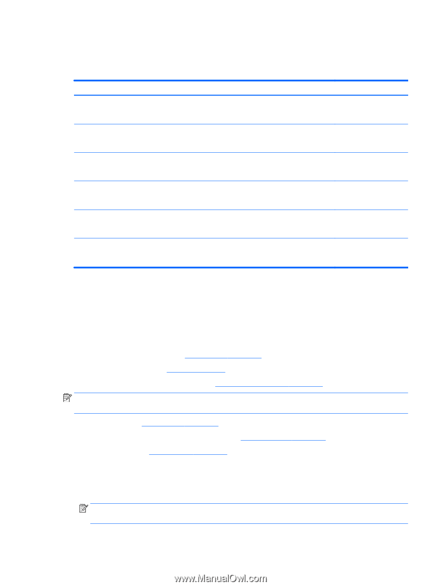
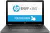
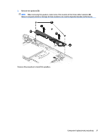
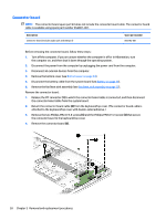
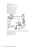
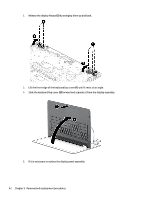
Reverse this procedure to install the connector board. System board Description Spare part number Equipped with an AMD FX-9800P 2.70-GHz (turbo up to 3.60-GHz) processor (1866-MHz FSB, 2.0-MB L2 cache, quad core, 15-W), 2.0-GB of system memory, a graphics subsystem with UMA memory, and the Windows 10 Professional operating system 856309-601 Equipped with an AMD FX-9800P 2.70-GHz (turbo up to 3.60-GHz) processor (1866-MHz FSB, 2.0-MB L2 cache, quad core, 15-W), 2.0-GB of system memory, a graphics subsystem with UMA memory, and a non-Windows operating system 856309-001 Equipped with an AMD FX-9800P 2.70-GHz (turbo up to 3.60-GHz) processor (1866-MHz FSB, 2.0-MB L2 cache, quad core, 15-W), 1.0-GB of system memory, a graphics subsystem with UMA memory, and the Windows 10 Professional operating system 856307-601 Equipped with an AMD FX-9800P 2.70-GHz (turbo up to 3.60-GHz) processor (1866-MHz FSB, 2.0-MB L2 cache, quad core, 15-W), 1.0-GB of system memory, a graphics subsystem with UMA memory, and a non-Windows operating system 856307-001 Equipped with an AMD A9-9400 2.90-GHz (turbo up to 3.5-GHz) processor (2133-MHz FSB, 1.0-MB L2 cache, dual core, 15-W), 1.0-GB of system memory, a graphics subsystem with UMA memory, and the Windows 10 Professional operating system 860072-601 Equipped with an AMD A9-9400 2.90-GHz (turbo up to 3.5-GHz) processor (2133-MHz FSB, 1.0-MB L2 860072-001 cache, dual core, 15-W), 1.0-GB of system memory, a graphics subsystem with UMA memory, and a nonWindows Professional operating system Before removing the system board, follow these steps: 1. Turn off the computer. If you are unsure whether the computer is off or in Hibernation, turn the computer on, and then shut it down through the operating system. 2. Disconnect the power from the computer by unplugging the power cord from the computer. 3. Disconnect all external devices from the computer. 4. Remove the bottom cover (see Bottom cover on page 24). 5. Remove the battery (see Battery on page 26). 6. Remove the fan/heat sink assembly (see Fan/heat sink assembly on page 35). NOTE: When replacing the system board, be sure that the following components are removed from the defective system board and installed on the replacement system board: ● RTC battery (see Bottom cover on page 24) ● Memory module shield and memory module (see Memory module on page 31) ● WLAN module (see WLAN module on page 32) Remove the system board: 1. Disconnect the following cables from the system board: (1) WLAN module antenna cables NOTE: The WLAN "Main/#1"antenna cable is connected to the WLAN module "Main" terminal. The WLAN "Aux/#2"antenna cable is connected to the WLAN module "Aux" terminal. Component replacement procedures 39
-
 1
1 -
2
-
3
-
4
-
5
-
6
-
7
-
8
-
9
-
10
-
11
-
12
-
13
-
14
-
15
-
16
-
17
-
18
-
19
-
20
-
21
-
22
-
23
-
24
-
25
-
26
-
27
-
28
-
29
-
30
-
31
-
32
-
33
-
34
-
35
-
36
-
37
-
38
-
39
-
40
-
41
-
 42
42 -
 43
43 -
 44
44 -
 45
45 -
 46
46 -
 47
47 -
 48
48 -
 49
49 -
 50
50 -
 51
51 -
 52
52 -
53
-
54
-
55
-
56
-
57
-
58
-
59
-
60
-
61
-
62
-
63
-
64
-
65
-
66
-
67
-
68
-
69
-
70
-
71
-
72
-
73
-
74
-
75
-
76
 |
 |