HP ENVY 15-ar000 Maintenance and Service Guide - Page 58
Power connector cable, Remove the two Phillips PM2.5×4.5 screws
 |
View all HP ENVY 15-ar000 manuals
Add to My Manuals
Save this manual to your list of manuals |
Page 58 highlights
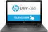
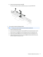
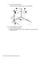
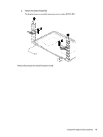
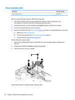
Power connector cable Description Power connector cable Spare part number 808155-011 Before removing the power connector cable, follow these steps: 1. Turn off the computer. If you are unsure whether the computer is off or in Hibernation, turn the computer on, and then shut it down through the operating system. 2. Disconnect the power from the computer by unplugging the power cord from the computer. 3. Disconnect all external devices from the computer. 4. Remove the bottom cover (see Bottom cover on page 24), and then removed the following components: a. Battery (see Battery on page 26). b. Fan/heat sink assembly (see Fan/heat sink assembly on page 35). c. System board (see System board on page 39). Remove the power connector cable: 1. Remove the two Phillips PM2.5×4.5 screws (1) that secure the left display hinge to the keyboard/ top cover. 2. Release the left display hinge (2) by swinging it up and back. 3. Remove the power connector cable (3). Reverse this procedure to install the power connector cable. 50 Chapter 5 Removal and replacement procedures
-
 1
1 -
2
-
3
-
4
-
5
-
6
-
7
-
8
-
9
-
10
-
11
-
12
-
13
-
14
-
15
-
16
-
17
-
18
-
19
-
20
-
21
-
22
-
23
-
24
-
25
-
26
-
27
-
28
-
29
-
30
-
31
-
32
-
33
-
34
-
35
-
36
-
37
-
38
-
39
-
40
-
41
-
42
-
43
-
44
-
45
-
46
-
47
-
48
-
49
-
50
-
51
-
52
-
 53
53 -
 54
54 -
 55
55 -
 56
56 -
 57
57 -
 58
58 -
 59
59 -
 60
60 -
 61
61 -
 62
62 -
 63
63 -
64
-
65
-
66
-
67
-
68
-
69
-
70
-
71
-
72
-
73
-
74
-
75
-
76
 |
 |