HP ENVY 15-ar000 Maintenance and Service Guide - Page 55
Release the pieces of tape, that secure the display panel cable to the display back cover.
 |
View all HP ENVY 15-ar000 manuals
Add to My Manuals
Save this manual to your list of manuals |
Page 55 highlights
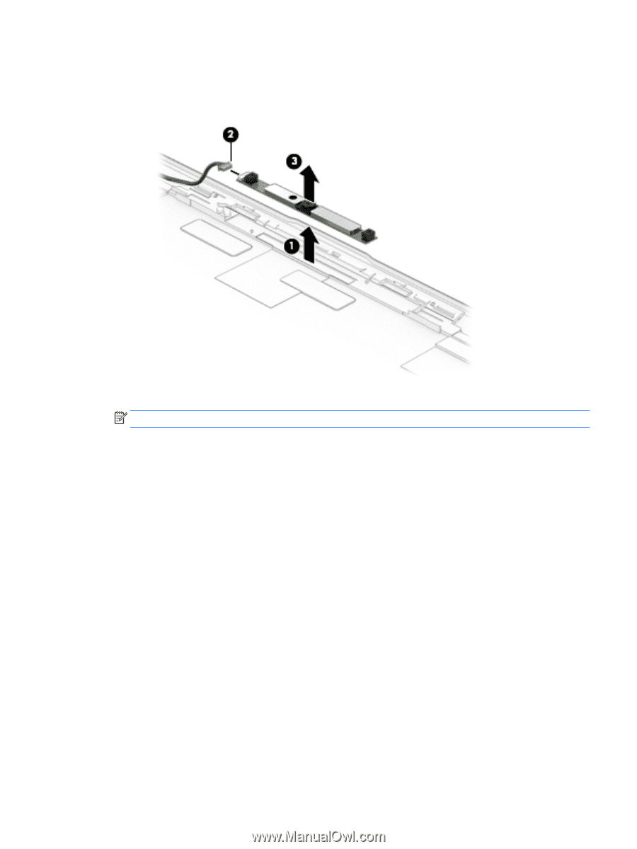
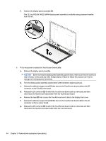
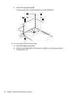
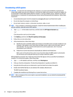
d. Remove the webcam/microphone module (3). The webcam/microphone module is available using spare part number 833962-005. 9. If it is necessary to replace the display panel cable: NOTE: The display panel cable includes the webcam/microphone module cable. a. Remove the display panel assembly. b. Disconnect the webcam/microphone module cable (1) from the webcam/microphone module. c. Release the pieces of tape (2) that secure the display panel cable to the display back cover. d. Release the grounding foil (3) that secures the display panel cable to the display back cover. e. Release the display panel cable from the routing clips (4) and channels built into the top, left, and bottom edges of the display back cover. Component replacement procedures 47
-
 1
1 -
2
-
3
-
4
-
5
-
6
-
7
-
8
-
9
-
10
-
11
-
12
-
13
-
14
-
15
-
16
-
17
-
18
-
19
-
20
-
21
-
22
-
23
-
24
-
25
-
26
-
27
-
28
-
29
-
30
-
31
-
32
-
33
-
34
-
35
-
36
-
37
-
38
-
39
-
40
-
41
-
42
-
43
-
44
-
45
-
46
-
47
-
48
-
49
-
 50
50 -
 51
51 -
 52
52 -
 53
53 -
 54
54 -
 55
55 -
 56
56 -
 57
57 -
 58
58 -
 59
59 -
 60
60 -
61
-
62
-
63
-
64
-
65
-
66
-
67
-
68
-
69
-
70
-
71
-
72
-
73
-
74
-
75
-
76
 |
 |