HP ENVY 15-ar000 Maintenance and Service Guide - Page 53
Detach the adhesive support strip
 |
View all HP ENVY 15-ar000 manuals
Add to My Manuals
Save this manual to your list of manuals |
Page 53 highlights
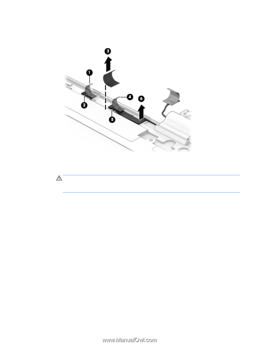
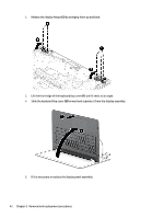
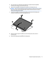
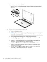
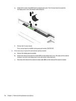
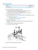
h. Remove the TouchScreen board cable (6). The TouchScreen board cable is available using spare part number 856803-001. 7. If it is necessary to replace the G-sensor board: a. Remove the display panel assembly. CAUTION: Before turning the display panel assembly upside down, make sure the work surface is clear of tools, screws, and any other foreign objects. Failure to follow this caution can result in damage to the display panel assembly. b. Turn the display panel assembly upside down with the bottom edge toward you. c. Detach the adhesive support strip (1) that secures the TouchScreen board cable to the ZIF connector on the G-sensor board. d. Release the ZIF connector (2) to which the TouchScreen board cable is connected, and then disconnect the TouchScreen board cable from the G-sensor board. Component replacement procedures 45
-
 1
1 -
2
-
3
-
4
-
5
-
6
-
7
-
8
-
9
-
10
-
11
-
12
-
13
-
14
-
15
-
16
-
17
-
18
-
19
-
20
-
21
-
22
-
23
-
24
-
25
-
26
-
27
-
28
-
29
-
30
-
31
-
32
-
33
-
34
-
35
-
36
-
37
-
38
-
39
-
40
-
41
-
42
-
43
-
44
-
45
-
46
-
47
-
 48
48 -
 49
49 -
 50
50 -
 51
51 -
 52
52 -
 53
53 -
 54
54 -
 55
55 -
 56
56 -
 57
57 -
 58
58 -
59
-
60
-
61
-
62
-
63
-
64
-
65
-
66
-
67
-
68
-
69
-
70
-
71
-
72
-
73
-
74
-
75
-
76
 |
 |