HP ENVY x2 - 15t-c000 HP ENVY x2 Detachable PC Maintenance and Service Guide - Page 60
System board, Disconnect the following cables from the system board
 |
View all HP ENVY x2 - 15t-c000 manuals
Add to My Manuals
Save this manual to your list of manuals |
Page 60 highlights
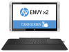
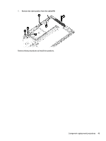
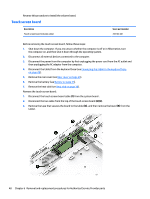
System board NOTE: The system board spare part kits include processor and replacement thermal material. Description System board for use with non-Windows 8 models; Intel Core M-5Y70 processor; 8 GB of system memory System board for use with Windows 8 Standard models; Intel Core M-5Y70 processor; 8 GB of system memory System board for use with non-Windows 8 models; Intel Core M-5Y70 processor; 4 GB of system memory System board for use with Windows 8 Standard models; Intel Core M-5Y70 processor; 4 GB of system memory System board for use with non-Windows 8 models; Intel Core M-5Y10 processor; 8 GB of system memory System board for use with Windows 8 Standard models; Intel Core M-5Y10 processor; 8 GB of system memory System board for use with non-Windows 8 models; Intel Core M-5Y10 processor; 4 GB of system memory System board for use with Windows 8 Standard models; Intel Core M-5Y10 processor; 4 GB of system memory Spare part number 783115-001 783115-501 783112-001 783112-501 783116-001 783116-501 783113-001 783113-501 Before removing the system board, follow these steps: 1. Shut down the computer. If you are unsure whether the computer is off or in Hibernation, turn the computer on, and then shut it down through the operating system. 2. Disconnect all external devices connected to the computer. 3. Disconnect the power from the computer by first unplugging the power cord from the AC outlet and then unplugging the AC adapter from the computer. 4. Disconnect the tablet from the keyboard base (see Connecting the tablet to the keyboard base on page 28). 5. Remove the rear cover (see Rear cover on page 29). 6. Remove the battery (see Battery on page 35). 7. Remove the heat sink (see Heat sink on page 38). 8. Remove the WLAN module (see WLAN/Bluetooth combo card on page 41). Remove the system board: 1. Disconnect the following cables from the system board: (1): Power button board cable (2): Touch board cable (3): Volume board cable (4): Card reader/audio board cable (5): Webcam cable (6): Left speaker cable 50 Chapter 6 Removal and replacement procedures for Authorized Service Provider parts
-
 1
1 -
2
-
3
-
4
-
5
-
6
-
7
-
8
-
9
-
10
-
11
-
12
-
13
-
14
-
15
-
16
-
17
-
18
-
19
-
20
-
21
-
22
-
23
-
24
-
25
-
26
-
27
-
28
-
29
-
30
-
31
-
32
-
33
-
34
-
35
-
36
-
37
-
38
-
39
-
40
-
41
-
42
-
43
-
44
-
45
-
46
-
47
-
48
-
49
-
50
-
51
-
52
-
53
-
54
-
 55
55 -
 56
56 -
 57
57 -
 58
58 -
 59
59 -
 60
60 -
 61
61 -
 62
62 -
 63
63 -
 64
64 -
 65
65 -
66
-
67
-
68
-
69
-
70
-
71
-
72
-
73
-
74
-
75
-
76
-
77
-
78
-
79
-
80
-
81
-
82
 |
 |