HP EliteBook 745 Maintenance and Service Guide - Page 63
RJ-45 board with bracket, Remove the RJ-45 board and bracket
 |
View all HP EliteBook 745 manuals
Add to My Manuals
Save this manual to your list of manuals |
Page 63 highlights
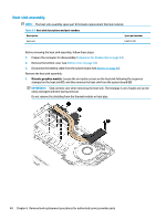
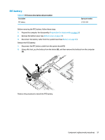
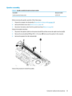
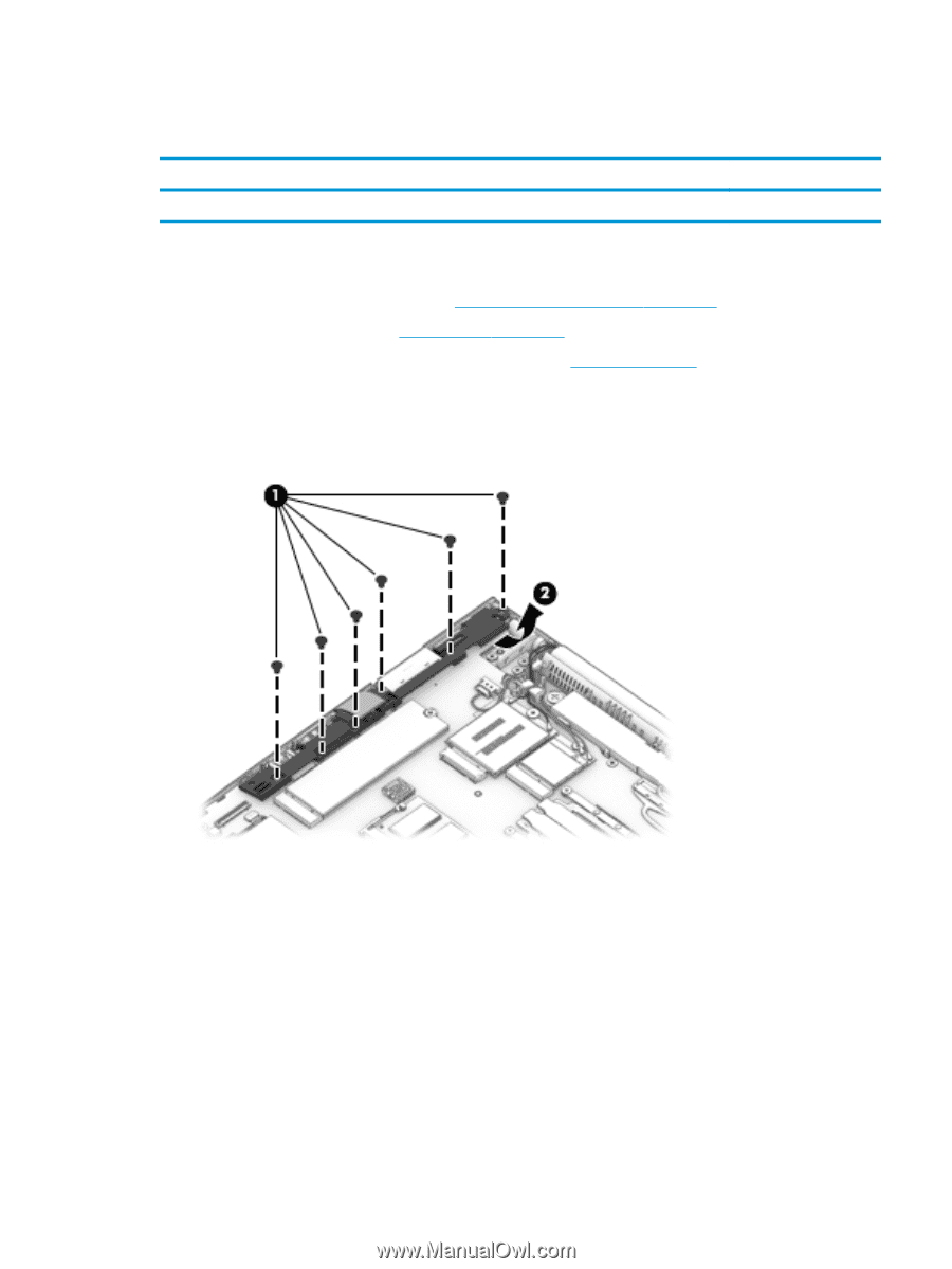
RJ-45 board with bracket Table 6-5 RJ-45 board with bracket description and part number Description RJ-45 board with bracket Spare part number L14386-001 Before removing the RJ-45 board and bracket, follow these steps: 1. Prepare the computer for disassembly (Preparation for disassembly on page 34). 2. Remove the bottom cover (see Bottom cover on page 34). 3. Disconnect the battery cable from the system board (see Battery on page 46). Remove the RJ-45 board and bracket: 1. Remove the six Phillips M2.5 × 5.0 screws (1) that secure the assembly to the computer. 2. Rotate the assembly out of the computer (2). Reverse this procedure to install the RJ-45 assembly. Component replacement procedures 53
-
 1
1 -
2
-
3
-
4
-
5
-
6
-
7
-
8
-
9
-
10
-
11
-
12
-
13
-
14
-
15
-
16
-
17
-
18
-
19
-
20
-
21
-
22
-
23
-
24
-
25
-
26
-
27
-
28
-
29
-
30
-
31
-
32
-
33
-
34
-
35
-
36
-
37
-
38
-
39
-
40
-
41
-
42
-
43
-
44
-
45
-
46
-
47
-
48
-
49
-
50
-
51
-
52
-
53
-
54
-
55
-
56
-
57
-
 58
58 -
 59
59 -
 60
60 -
 61
61 -
 62
62 -
 63
63 -
 64
64 -
 65
65 -
 66
66 -
 67
67 -
 68
68 -
69
-
70
-
71
-
72
-
73
-
74
-
75
-
76
-
77
-
78
-
79
-
80
-
81
-
82
-
83
-
84
-
85
-
86
-
87
-
88
-
89
-
90
-
91
-
92
-
93
-
94
-
95
-
96
-
97
-
98
-
99
-
100
-
101
-
102
-
103
-
104
-
105
-
106
-
107
-
108
-
109
-
110
-
111
-
112
-
113
-
114
-
115
-
116
-
117
-
118
-
119
 |
 |
RJ-45 board with bracket
Table 6-5
RJ-45 board with bracket description and part number
Description
Spare part number
RJ-45 board with bracket
L14386-001
Before removing the RJ-45 board and bracket, follow these steps:
1.
Prepare the computer for disassembly (
Preparation for disassembly
on page
34
).
2.
Remove the bottom cover (see
Bottom cover
on page
34
).
3.
Disconnect the battery cable from the system board (see
Battery
on page
46
).
Remove the RJ-45 board and bracket:
1.
Remove the six Phillips M2.5 × 5.0 screws
(1)
that secure the assembly to the computer.
2.
Rotate the assembly out of the computer
(2)
.
Reverse this procedure to install the RJ-45 assembly.
Component replacement procedures
53