HP EliteBook 745 Maintenance and Service Guide - Page 88
Interpreting system validation diagnostic front panel LEDs and audible codes
 |
View all HP EliteBook 745 manuals
Add to My Manuals
Save this manual to your list of manuals |
Page 88 highlights
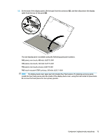
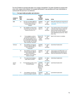
7 Interpreting system validation diagnostic front panel LEDs and audible codes During the system validation phase that occurs at system startup, the BIOS validates the functionality of the following subsystems and conditions: ● AC adapter ● System board power ● Processor failure ● BIOS corruption ● Memory failure ● Graphics failure ● System board failure ● BIOS authentication failure If an error is detected, specific patterns of long and short blinks, accompanied by long and short beeps (where applicable) are used to identify the error. These patterns will make up a two part code: ● Major - the category of the error ● Minor - the specific error within the category NOTE: Codes with a single blink or beep are not used. Table 7-1 Front panel LEDs and audible codes Number of long beeps/blinks Error category 1 Not used 2 BIOS 3 Hardware 4 Thermal 5 System board Patterns of blink or beep codes are determined by using the following parameters: ● 1 second pause occurs after the last major blink. ● 2 second pause occurs after the last minor blink. ● Beep error code sequences occur for the first 5 iterations of the pattern and then stop. ● Blink error code sequences continue until the computer is unplugged or the power button is pressed. NOTE: Not all diagnostic lights and audible codes are available on all models. 78 Chapter 7 Interpreting system validation diagnostic front panel LEDs and audible codes
-
 1
1 -
2
-
3
-
4
-
5
-
6
-
7
-
8
-
9
-
10
-
11
-
12
-
13
-
14
-
15
-
16
-
17
-
18
-
19
-
20
-
21
-
22
-
23
-
24
-
25
-
26
-
27
-
28
-
29
-
30
-
31
-
32
-
33
-
34
-
35
-
36
-
37
-
38
-
39
-
40
-
41
-
42
-
43
-
44
-
45
-
46
-
47
-
48
-
49
-
50
-
51
-
52
-
53
-
54
-
55
-
56
-
57
-
58
-
59
-
60
-
61
-
62
-
63
-
64
-
65
-
66
-
67
-
68
-
69
-
70
-
71
-
72
-
73
-
74
-
75
-
76
-
77
-
78
-
79
-
80
-
81
-
82
-
 83
83 -
 84
84 -
 85
85 -
 86
86 -
 87
87 -
 88
88 -
 89
89 -
 90
90 -
 91
91 -
 92
92 -
 93
93 -
94
-
95
-
96
-
97
-
98
-
99
-
100
-
101
-
102
-
103
-
104
-
105
-
106
-
107
-
108
-
109
-
110
-
111
-
112
-
113
-
114
-
115
-
116
-
117
-
118
-
119
 |
 |