HP EliteBook 745 Maintenance and Service Guide - Page 71
Fan, Position the computer upright and open as far as possible.
 |
View all HP EliteBook 745 manuals
Add to My Manuals
Save this manual to your list of manuals |
Page 71 highlights
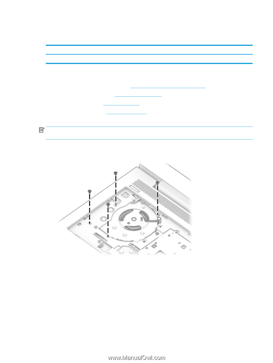
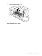
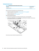
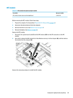
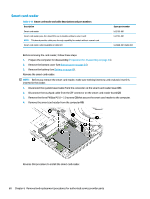
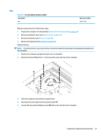
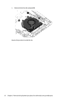
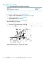
Fan Table 6-12 Fan description and part number Description Fan Spare part number L62739-001 Before removing the fan, follow these steps: 1. Prepare the computer for disassembly (Preparation for disassembly on page 34). 2. Remove the bottom cover (see Bottom cover on page 34). 3. Remove the battery (see Battery on page 46). 4. Remove the keyboard (see Keyboard on page 42). Remove the fan: NOTE: To remove the fan, you must remove screws from both the top (under the keyboard) and bottom of the computer. 1. Position the computer upright and open as far as possible. 2. Remove the four Phillips M2.0 × 3.0 screws that secure the fan to the computer. 3. Close the computer and position it upside down. 4. Disconnect the fan cable from the system board (1). 5. Loosen the two captive Phillips screws (2) that secure the fan to the computer. Component replacement procedures 61
-
 1
1 -
2
-
3
-
4
-
5
-
6
-
7
-
8
-
9
-
10
-
11
-
12
-
13
-
14
-
15
-
16
-
17
-
18
-
19
-
20
-
21
-
22
-
23
-
24
-
25
-
26
-
27
-
28
-
29
-
30
-
31
-
32
-
33
-
34
-
35
-
36
-
37
-
38
-
39
-
40
-
41
-
42
-
43
-
44
-
45
-
46
-
47
-
48
-
49
-
50
-
51
-
52
-
53
-
54
-
55
-
56
-
57
-
58
-
59
-
60
-
61
-
62
-
63
-
64
-
65
-
 66
66 -
 67
67 -
 68
68 -
 69
69 -
 70
70 -
 71
71 -
 72
72 -
 73
73 -
 74
74 -
 75
75 -
 76
76 -
77
-
78
-
79
-
80
-
81
-
82
-
83
-
84
-
85
-
86
-
87
-
88
-
89
-
90
-
91
-
92
-
93
-
94
-
95
-
96
-
97
-
98
-
99
-
100
-
101
-
102
-
103
-
104
-
105
-
106
-
107
-
108
-
109
-
110
-
111
-
112
-
113
-
114
-
115
-
116
-
117
-
118
-
119
 |
 |