HP EliteBook 745 Maintenance and Service Guide - Page 89
The red LED blinks to represent the major error category long blinks. The white LED blinks to represent
 |
View all HP EliteBook 745 manuals
Add to My Manuals
Save this manual to your list of manuals |
Page 89 highlights
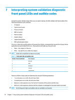
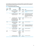
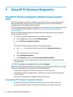
The red LED blinks to represent the major error category (long blinks). The white LED blinks to represent the minor error category (short blinks). For example, 3.5 indicates 3 long red blinks and 5 short white blinks to communicate the processor is not detected. Table 7-2 Front panel LEDs and audible code indications Component tested Major/ minor code Error condition Notebook Caps Lock/Num Lock LED Desktop Action BIOS 2.2 The main area (DXE) of BIOS has CAP/NUM 2.2 - Power Follow the Crisis Recovery instructions at become corrupted and there is Blink = 2 LED http://support.hp.com/us-en/document/ no recovery binary image (red.white) c02693833/. available 2.3 The embedded controller policy CAP/NUM 2.3 - Power If you want an analysis of the event that requires the user to enter a key Blink = 8 LED caused Sure Start recovery, replace the sequence (SureStart 2.0) (red.white) board and send the bad board back. Otherwise, press this key combination to restore BIOS and boot: Up Arrow + Down Arrow + Esc. 2.4 The embedded controller is Battery LED 2.4 - Power Wait for DXE recovery to complete. recovering the boot block or White and LED DXE. Because it takes 10 sec or Amber (red.white) so to load the DXE image and get blinking video in the DXE case, this blink code is necessary. (SureStart) Hardware 3.2 The embedded controller has CAP/NUM 3.2 - Power System board replacement. timed out waiting for BIOS to Blink = 3 LED return from memory (red.white) initialization 3.3 The embedded controller has CAP/NUM 3.3 - Power If the system has an MXM module, try a timed out waiting for BIOS to Blink = 4 LED different MXM module. Otherwise, the return from graphics (red.white) board most likely needs to be replaced. initialization ( 4/13- Graphics adaptor not found) 3.4 The system board displays a CAP/NUM 3.4 - Power System board replacement. power failure (crowbar) * Blink = 5 LED (red.white) System board 5.2 The embedded controller cannot CAP/NUM 5.2 - Power System board replacement. find valid firmware Blink = 7 (2 LED BB failure) (red.white) Battery LED Blinking = 1 Hz (3 B failure) 5.3 The embedded controller has CAP/NUM Not System board replacement. timed out waiting for the BIOS Blink = 1 implemented 79
-
 1
1 -
2
-
3
-
4
-
5
-
6
-
7
-
8
-
9
-
10
-
11
-
12
-
13
-
14
-
15
-
16
-
17
-
18
-
19
-
20
-
21
-
22
-
23
-
24
-
25
-
26
-
27
-
28
-
29
-
30
-
31
-
32
-
33
-
34
-
35
-
36
-
37
-
38
-
39
-
40
-
41
-
42
-
43
-
44
-
45
-
46
-
47
-
48
-
49
-
50
-
51
-
52
-
53
-
54
-
55
-
56
-
57
-
58
-
59
-
60
-
61
-
62
-
63
-
64
-
65
-
66
-
67
-
68
-
69
-
70
-
71
-
72
-
73
-
74
-
75
-
76
-
77
-
78
-
79
-
80
-
81
-
82
-
83
-
 84
84 -
 85
85 -
 86
86 -
 87
87 -
 88
88 -
 89
89 -
 90
90 -
 91
91 -
 92
92 -
 93
93 -
 94
94 -
95
-
96
-
97
-
98
-
99
-
100
-
101
-
102
-
103
-
104
-
105
-
106
-
107
-
108
-
109
-
110
-
111
-
112
-
113
-
114
-
115
-
116
-
117
-
118
-
119
 |
 |