HP Indigo 10000 B&R Drivers Troubleshooting -- Document P/N:CA493-00610 Re - Page 23
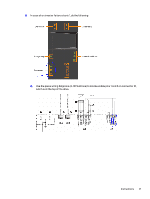
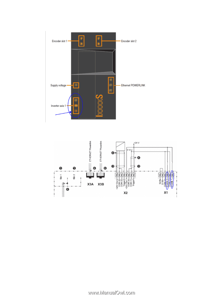
Use the press wiring diagrams in CE Suitcase to locate enable pins 1 and 3 on connector X1
 |
View all HP Indigo 10000 manuals
Add to My Manuals
Save this manual to your list of manuals |
Page 23 highlights
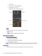
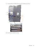
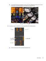
4. In case of an inverter failure at axis 1, do the following a. Use the press wiring diagrams (in CE Suitcase) to locate enable pins 1 and 3 on connector X1, which is at the top of the drive. Instructions 21
-
 1
1 -
2
-
3
-
4
-
5
-
6
-
7
-
8
-
9
-
10
-
11
-
12
-
13
-
14
-
15
-
16
-
17
-
 18
18 -
 19
19 -
 20
20 -
 21
21 -
 22
22 -
 23
23 -
 24
24 -
 25
25 -
 26
26 -
 27
27 -
 28
28 -
29
-
30
-
31
-
32
-
33
-
34
-
35
-
36
-
37
-
38
-
39
-
40
-
41
-
42
-
43
-
44
-
45
-
46
-
47
-
48
-
49
-
50
-
51
-
52
-
53
-
54
-
55
-
56
-
57
-
58
-
59
-
60
-
61
 |
 |
4.
In case of an inverter failure at axis 1, do the following
a.
Use the press wiring diagrams (in CE Suitcase) to locate enable pins 1 and 3 on connector X1,
which is at the top of the drive.
Instructions
21