HP Indigo 10000 B&R Drivers Troubleshooting -- Document P/N:CA493-00610 Re - Page 32
Using the diagram, check that other power link components receive power.
 |
View all HP Indigo 10000 manuals
Add to My Manuals
Save this manual to your list of manuals |
Page 32 highlights
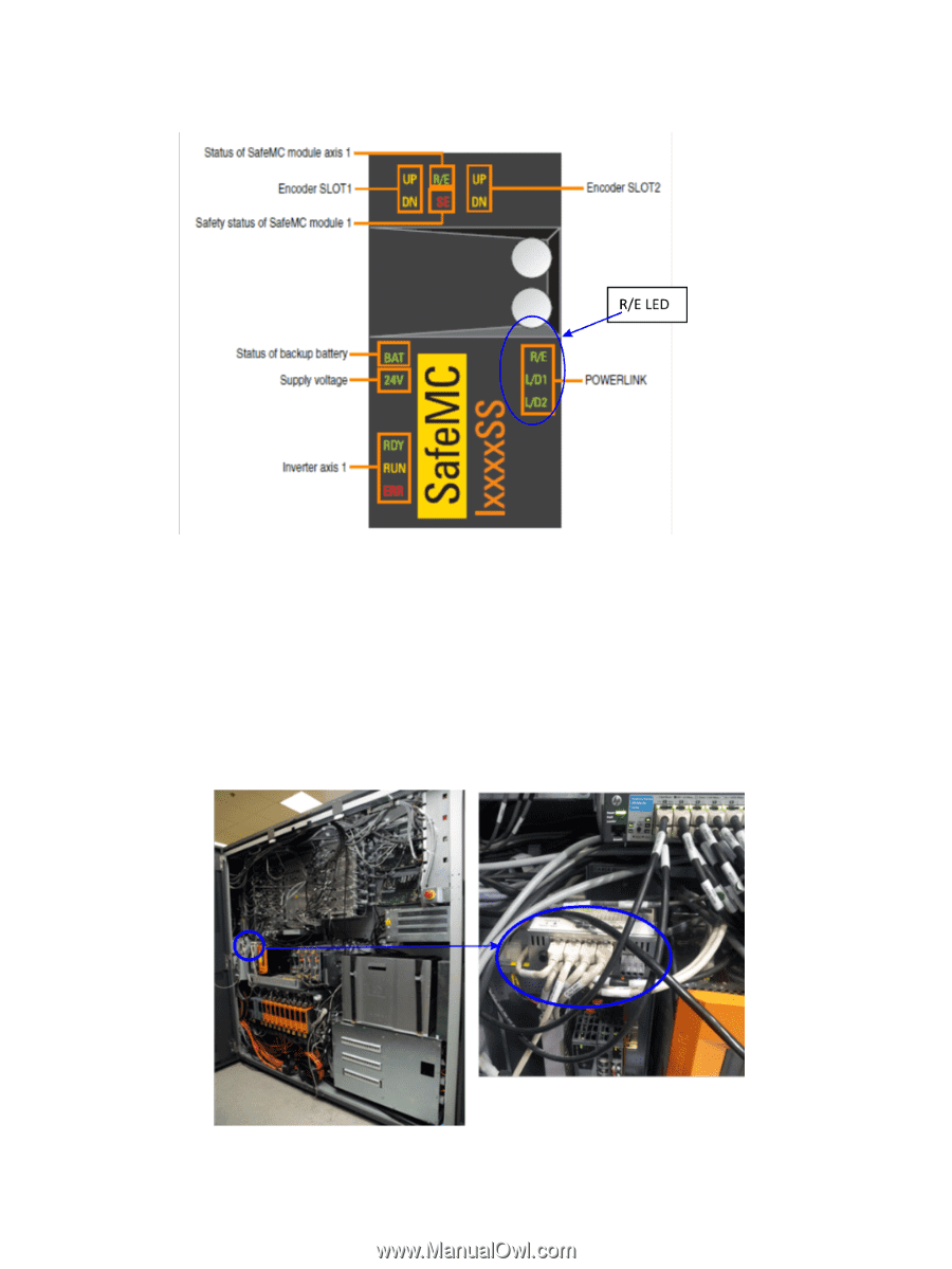
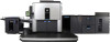
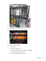
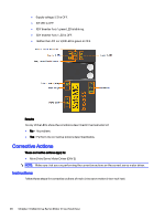
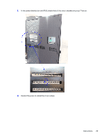
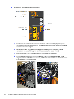
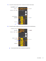
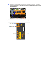
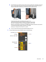
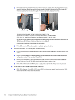
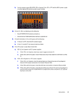
3. In case of a POWERLINK failure, do the following: a. Use the relevant communications/network schematic in the press wiring diagrams (in CE Suitcase) to check the cables. Search for the specific servo motor driver branch to locate the relevant cables in the diagram. b. On the press, check the integrity of the cables and connectors and make sure that the connections are correct through the branch. Replace defective cables if found. c. Using the diagram, check that other power link components receive power. d. If the power link components do not receive power, check the powerlink hub (refer to the diagram) and ensure the hub receives power, and the relevant port LED (use scheme to locate) is blinking green (connection active). 30 Chapter 4 Main Drive Servo Motor Driver Multi Test
-
 1
1 -
2
-
3
-
4
-
5
-
6
-
7
-
8
-
9
-
10
-
11
-
12
-
13
-
14
-
15
-
16
-
17
-
18
-
19
-
20
-
21
-
22
-
23
-
24
-
25
-
26
-
 27
27 -
 28
28 -
 29
29 -
 30
30 -
 31
31 -
 32
32 -
 33
33 -
 34
34 -
 35
35 -
 36
36 -
 37
37 -
38
-
39
-
40
-
41
-
42
-
43
-
44
-
45
-
46
-
47
-
48
-
49
-
50
-
51
-
52
-
53
-
54
-
55
-
56
-
57
-
58
-
59
-
60
-
61
 |
 |