HP Kayak XU 03xx HP Kayak XU Series 03xx, Familiarization guide - Page 13
Error Code, Action to Take, Compatibility of DIMMs. The BIOS checks
 |
View all HP Kayak XU 03xx manuals
Add to My Manuals
Save this manual to your list of manuals |
Page 13 highlights
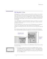
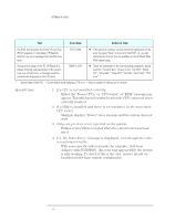
HP MaxiLife Utility Test Error Code Action to Take 1 When pressing one of the LCD status panel buttons, nothing is displayed. 2 When the system is powered on, nothing is displayed. Presence of either CPU or Terminator in the processor slot. Control of some voltages: VRMs, 12V Number of installed DIMMs Compatibility of DIMMs. The BIOS checks that the inserted DIMMs are both compatible with one another, and compatible with the Front Side Bus frequency. Check the system board clock generators (PLL). Test of the correct power signals to the CPU. The power supply may be OK, whereas the VRM is not. Availability of video controller. It is also checked by the BIOS. If an error is detected, it is not a fatal one and the BIOS will continue its execution normally. In order to detect whether the CPU is able to run a given code, HP MaxiLife waits for a synchronization event from the BIOS. Any failure that prevents the execution of the firmware will trigger an error. LCD status panel is blank • Check that the two cables to the LCD status panel are properly connected (refer to the system board layout for position). • Check that the PC's power cable is plugged in. CPU SOCKET • Check CPUs and Terminator and VRM of installed processor. POWER SUPPLY NO RAM RAM TYPE BOARD PLL POWER NO VIDEO • Check the power supply connectors, VRM, CPU. In a single processor system, check that the VRM is not plugged into the terminator socket. The error message could also show: Power CPU1 and Power CPU2. • Check that the memory module is correctly installed in the memory socket. • Check the installed memory modules. This error occurs when mixing incompatible memory modules, for example, when installing a 66 MHz DIMM on a 350 MHz or higher system, or when mixing Unbuffered and Registered memory modules. • Check the power supply connector. • Replace the system board (PLL clock generator). • Check that the VRM, processor and terminator are correctly installed. • Check that the VRM is not plugged on a socket with a terminator (this could be the likely cause). • Check or replace the VRM. • Check the power supply unit connectors. • Check that the video controller is correctly installed. Note: No error is detected if a monitor is not connected to an installed video controller. BIOS • Flash the latest version of the system BIOS by using the system recovery procedure. Set switch 10 to the down position. • Check that the RAM is correctly installed. • Check that the CPU is firmly inserted. 13
-
 1
1 -
2
-
3
-
4
-
5
-
6
-
7
-
 8
8 -
 9
9 -
 10
10 -
 11
11 -
 12
12 -
 13
13 -
 14
14 -
 15
15 -
 16
16 -
 17
17 -
 18
18 -
19
-
20
-
21
-
22
-
23
-
24
-
25
-
26
-
27
-
28
-
29
-
30
-
31
-
32
-
33
-
34
-
35
-
36
-
37
-
38
-
39
-
40
-
41
-
42
-
43
-
44
 |
 |