HP Kayak XU 03xx HP Kayak XU Series 03xx, Familiarization guide - Page 9
System Board Layouts, HP Kayak XU and XW System Board Layout
 |
View all HP Kayak XU 03xx manuals
Add to My Manuals
Save this manual to your list of manuals |
Page 9 highlights
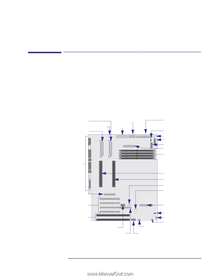
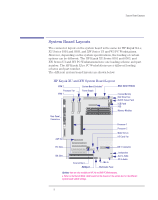
System Board Layouts System Board Layouts The connector layout on the system board is the same for HP Kayak XA-s, XU Series 0301 and 0303, and XW Series U3 and W3 PC Workstations. However, depending on the system specifications, the loading of certain options can be different. The HP Kayak XU Series 0301 and 0303, and XW Series U3 and W3 PC Workstations have one loading scheme and part number. The HP Kayak XA-s PC Workstations use a different loading scheme and part number. The different system board layouts are shown below: HP Kayak XU and XW System Board Layout VRM 2 Processor Fan VRM 1 System Board Switchesa Power Supply Rear Panel Connectors Wide SCSI (16-bits) External Battery Disk Drive Fans On/Off Status Panel LCD Panel FDD 4 3 Memory Modules 2 1 AGP Slot Processor 1 Processor 2 Wake On Lan I/O Cards Fan PCI Slots IDE 1 Connector ISA Slots External Start RAIDport Mic In Multimedia Panel Loudspeaker Aux In Audio CD In Audio Options that are only available on HP XU and XW PC Workstations. a. Refer to the Switch Block Label located on the chassis of the system box for the different system board switch settings. 9
-
 1
1 -
2
-
3
-
 4
4 -
 5
5 -
 6
6 -
 7
7 -
 8
8 -
 9
9 -
 10
10 -
 11
11 -
 12
12 -
 13
13 -
 14
14 -
15
-
16
-
17
-
18
-
19
-
20
-
21
-
22
-
23
-
24
-
25
-
26
-
27
-
28
-
29
-
30
-
31
-
32
-
33
-
34
-
35
-
36
-
37
-
38
-
39
-
40
-
41
-
42
-
43
-
44
 |
 |