HP Nc4000 Maintenance and Service Guide: HP Compaq Notebook nc4000 Series - Page 116
System Board, Spare Part Number Information
 |
View all HP Nc4000 manuals
Add to My Manuals
Save this manual to your list of manuals |
Page 116 highlights
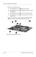
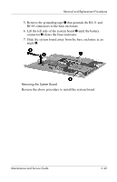
Removal and Replacement Procedures 5.19 System Board System board System Board Spare Part Number Information 325514-001 ✎ When replacing the system board, ensure that the following components are removed from the defective system board and installed on the replacement system board: ■ Memory expansion boards (Section 5.5) ■ Mini PCI communications board (Section 5.6) ■ Processor (Section 5.11) ■ Modem and modem cable (Section 5.18) 1. Prepare the notebook for disassembly (Section 5.3) and remove the following components: ❏ LED switch cover (Section 5.7) ❏ Keyboard (Section 5.8) ❏ Heat sink and fan (Section 5.10) ❏ Display assembly (Section 5.12) ❏ Top cover (Section 5.13) ❏ Switch board (Section 5.16) 2. Position the base enclosure so the rear panel is facing forward. Maintenance and Service Guide 5-43
-
 1
1 -
2
-
3
-
4
-
5
-
6
-
7
-
8
-
9
-
10
-
11
-
12
-
13
-
14
-
15
-
16
-
17
-
18
-
19
-
20
-
21
-
22
-
23
-
24
-
25
-
26
-
27
-
28
-
29
-
30
-
31
-
32
-
33
-
34
-
35
-
36
-
37
-
38
-
39
-
40
-
41
-
42
-
43
-
44
-
45
-
46
-
47
-
48
-
49
-
50
-
51
-
52
-
53
-
54
-
55
-
56
-
57
-
58
-
59
-
60
-
61
-
62
-
63
-
64
-
65
-
66
-
67
-
68
-
69
-
70
-
71
-
72
-
73
-
74
-
75
-
76
-
77
-
78
-
79
-
80
-
81
-
82
-
83
-
84
-
85
-
86
-
87
-
88
-
89
-
90
-
91
-
92
-
93
-
94
-
95
-
96
-
97
-
98
-
99
-
100
-
101
-
102
-
103
-
104
-
105
-
106
-
107
-
108
-
109
-
110
-
 111
111 -
 112
112 -
 113
113 -
 114
114 -
 115
115 -
 116
116 -
 117
117 -
 118
118 -
 119
119 -
 120
120 -
 121
121 -
122
-
123
-
124
-
125
-
126
-
127
-
128
-
129
-
130
-
131
-
132
-
133
-
134
-
135
-
136
-
137
-
138
-
139
-
140
-
141
-
142
-
143
-
144
-
145
-
146
-
147
-
148
-
149
-
150
-
151
-
152
-
153
-
154
-
155
-
156
-
157
-
158
-
159
-
160
-
161
-
162
-
163
-
164
-
165
-
166
-
167
 |
 |
