HP OMEN 15-ce100 Maintenance and Service Guide - Page 83
panel from the display assembly at this time.
 |
View all HP OMEN 15-ce100 manuals
Add to My Manuals
Save this manual to your list of manuals |
Page 83 highlights
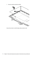
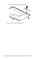
2. Remove the brackets from the display assembly (2). 3. Remove the four Phillips PM1.9×3.5 screws (1) that secure the display panel to the display assembly. 4. Turn the display panel over face down (2). IMPORTANT: To avoid damaging the display panel or display panel cable, do not remove the display panel from the display assembly at this time. 5. Remove the adhesive tape from the display panel connector (1). Component replacement procedures 73
-
 1
1 -
2
-
3
-
4
-
5
-
6
-
7
-
8
-
9
-
10
-
11
-
12
-
13
-
14
-
15
-
16
-
17
-
18
-
19
-
20
-
21
-
22
-
23
-
24
-
25
-
26
-
27
-
28
-
29
-
30
-
31
-
32
-
33
-
34
-
35
-
36
-
37
-
38
-
39
-
40
-
41
-
42
-
43
-
44
-
45
-
46
-
47
-
48
-
49
-
50
-
51
-
52
-
53
-
54
-
55
-
56
-
57
-
58
-
59
-
60
-
61
-
62
-
63
-
64
-
65
-
66
-
67
-
68
-
69
-
70
-
71
-
72
-
73
-
74
-
75
-
76
-
77
-
 78
78 -
 79
79 -
 80
80 -
 81
81 -
 82
82 -
 83
83 -
 84
84 -
 85
85 -
 86
86 -
 87
87 -
 88
88 -
89
-
90
-
91
-
92
-
93
-
94
-
95
-
96
-
97
-
98
-
99
-
100
-
101
-
102
-
103
-
104
-
105
-
106
-
107
-
108
 |
 |

2.
Remove the brackets from the display assembly
(2)
.
3.
Remove the four Phillips PM1.9×3.5 screws
(1)
that secure the display panel to the display assembly.
4.
Turn the display panel over face down
(2)
.
IMPORTANT:
To avoid damaging the display panel or display panel cable, do not remove the display
panel from the display assembly at this time.
5.
Remove the adhesive tape from the display panel connector
(1)
.
Component replacement procedures
73