HP Pavilion 13-s000 Maintenance and Service Guide - Page 42
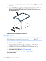
Disconnect the following cables from the system board, built into the fan/heat sink assembly.
 |
View all HP Pavilion 13-s000 manuals
Add to My Manuals
Save this manual to your list of manuals |
Page 42 highlights
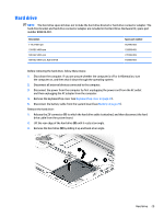
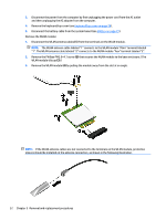
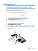
3. Disconnect the power from the computer by first unplugging the power cord from the AC outlet and then unplugging the AC adapter from the computer. 4. Remove the keyboard/top cover (see Keyboard/top cover on page 24). 5. Disconnect the battery cable from the system board (see Battery on page 27). 6. Remove the WLAN module (see WLAN module on page 31). When replacing the system board, be sure that the fan/heat sink assembly (see Fan/heat sink assembly on page 37) and the memory modules (see Memory module on page 38) are removed from the defective system board and installed on the replacement system board. Remove the system board: 1. Release the wireless antenna cables from the retention clips (1) built into the fan/heat sink assembly. 2. Disconnect the following cables from the system board: (2) Display panel cable from the ZIF connector on the system board (3) Power button board cable from the ZIF connector on the system board (4) Connector board cable from the ZIF connector on the system board 34 Chapter 5 Removal and replacement procedures
-
 1
1 -
2
-
3
-
4
-
5
-
6
-
7
-
8
-
9
-
10
-
11
-
12
-
13
-
14
-
15
-
16
-
17
-
18
-
19
-
20
-
21
-
22
-
23
-
24
-
25
-
26
-
27
-
28
-
29
-
30
-
31
-
32
-
33
-
34
-
35
-
36
-
 37
37 -
 38
38 -
 39
39 -
 40
40 -
 41
41 -
 42
42 -
 43
43 -
 44
44 -
 45
45 -
 46
46 -
 47
47 -
48
-
49
-
50
-
51
-
52
-
53
-
54
-
55
-
56
-
57
-
58
-
59
-
60
-
61
-
62
-
63
-
64
-
65
-
66
-
67
-
68
-
69
-
70
-
71
-
72
-
73
-
74
-
75
-
76
-
77
-
78
-
79
-
80
-
81
-
82
-
83
-
84
-
85
-
86
-
87
-
88
 |
 |
