HP Pavilion 13-s000 Maintenance and Service Guide - Page 43
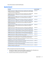
the system board to the base enclosure., and the Phillips PM2.0×4.1 screw
 |
View all HP Pavilion 13-s000 manuals
Add to My Manuals
Save this manual to your list of manuals |
Page 43 highlights
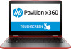
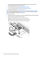
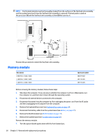
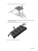
3. Disconnect the following cables from the system board: (1) Webcam/microphone cable (2) Power connector cable (3) Speaker cable (4) Hard drive cable from the ZIF connector on the system board 4. Remove the six Phillips PM2.5×4.4 screws (1) and the Phillips PM2.0×4.1 screw (2) that secure the system board to the base enclosure. 5. Lift the front edge of the system board (1) until it rests at an angle. System board 35
-
 1
1 -
2
-
3
-
4
-
5
-
6
-
7
-
8
-
9
-
10
-
11
-
12
-
13
-
14
-
15
-
16
-
17
-
18
-
19
-
20
-
21
-
22
-
23
-
24
-
25
-
26
-
27
-
28
-
29
-
30
-
31
-
32
-
33
-
34
-
35
-
36
-
37
-
 38
38 -
 39
39 -
 40
40 -
 41
41 -
 42
42 -
 43
43 -
 44
44 -
 45
45 -
 46
46 -
 47
47 -
 48
48 -
49
-
50
-
51
-
52
-
53
-
54
-
55
-
56
-
57
-
58
-
59
-
60
-
61
-
62
-
63
-
64
-
65
-
66
-
67
-
68
-
69
-
70
-
71
-
72
-
73
-
74
-
75
-
76
-
77
-
78
-
79
-
80
-
81
-
82
-
83
-
84
-
85
-
86
-
87
-
88
 |
 |
3.
Disconnect the following cables from the system board:
(1)
Webcam/microphone cable
(2)
Power connector cable
(3)
Speaker cable
(4)
Hard drive cable from the ZIF connector on the system board
4.
Remove the six Phillips PM2.5×4.4 screws
(1)
and the Phillips PM2.0×4.1 screw
(2)
that secure
the system board to the base enclosure.
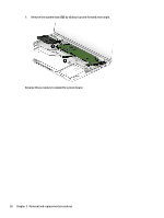
5.
Lift the front edge of the system board
(1)
until it rests at an angle.
System board
35