HP Pavilion 14-al000 Maintenance and Service Guide - Page 53
Disconnect the following cables from the system board, Hard drive ZIF connector cable
 |
View all HP Pavilion 14-al000 manuals
Add to My Manuals
Save this manual to your list of manuals |
Page 53 highlights
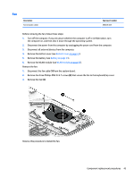
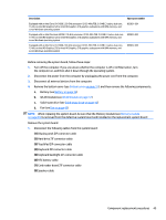
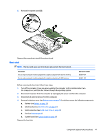
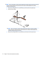
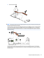
Description Spare part number Equipped with an Intel Core i3-6100U 2.30-GHz processor (2133-MHz FSB, 3.0-MB L3 cache, dual core, 15-W), an Intel HD Graphics 520 or Intel HD Graphics 510 graphics subsystem with UMA memory, and a non-Windows operating system 855831-001 Equipped with an Intel Pentium 4405U 2.10-GHz processor (2133-MHz FSB, 2.0-MB L3 cache, dual core, 15-W), an Intel HD Graphics 520 or Intel HD Graphics 510 graphics subsystem with UMA memory, and a non-Windows operating system 855832-001 Equipped with an Intel Core i3-6100U 2.30-GHz processor (2133-MHz FSB, 3.0-MB L3 cache, dual core, 15-W), an Intel HD Graphics 520 or Intel HD Graphics 510 graphics subsystem with UMA memory, and a non-Windows operating system 855832-001 Before removing the system board, follow these steps: 1. Turn off the computer. If you are unsure whether the computer is off or in Hibernation, turn the computer on, and then shut it down through the operating system. 2. Disconnect the power from the computer by unplugging the power cord from the computer. 3. Disconnect all external devices from the computer. 4. Remove the bottom cover (see Bottom cover on page 31), and then remove the following components: a. Battery (see Battery on page 33) b. WLAN module (see WLAN module on page 37) c. Solid-state drive (see Solid-state drive on page 42) d. Fan (see Fan on page 43) NOTE: When replacing the system board, be sure that the Memory module (see Memory module on page 36) is removed from the defective system board and installed on the replacement system board: Remove the system board: 1. Disconnect the following cables from the system board: (1) Display panel ZIF connector cable (2) Hard drive ZIF connector cable (3) TouchPad ZIF connector cable (4) Keyboard ZIF connector cable (5) Keyboard backlight ZIF connector cable (6) RTC battery cable (7) Card reader board ZIF connector cable (8) Speaker cable Component replacement procedures 45
-
 1
1 -
2
-
3
-
4
-
5
-
6
-
7
-
8
-
9
-
10
-
11
-
12
-
13
-
14
-
15
-
16
-
17
-
18
-
19
-
20
-
21
-
22
-
23
-
24
-
25
-
26
-
27
-
28
-
29
-
30
-
31
-
32
-
33
-
34
-
35
-
36
-
37
-
38
-
39
-
40
-
41
-
42
-
43
-
44
-
45
-
46
-
47
-
 48
48 -
 49
49 -
 50
50 -
 51
51 -
 52
52 -
 53
53 -
 54
54 -
 55
55 -
 56
56 -
 57
57 -
 58
58 -
59
-
60
-
61
-
62
-
63
-
64
-
65
-
66
-
67
-
68
-
69
-
70
-
71
-
72
-
73
-
74
-
75
-
76
-
77
-
78
-
79
-
80
-
81
-
82
-
83
-
84
-
85
-
86
-
87
 |
 |
