HP Pavilion 14-al000 Maintenance and Service Guide - Page 62
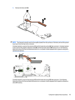
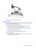
Release the display hinges, by swinging them up and back.
 |
View all HP Pavilion 14-al000 manuals
Add to My Manuals
Save this manual to your list of manuals |
Page 62 highlights
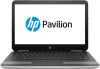
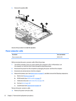
2. Disconnect the WLAN antenna cables (2) from the terminals on the WLAN module. NOTE: The WLAN antenna cable labeled "1/MAIN" connects to the WLAN module "Main" terminal. The WLAN antenna cable labeled "2/AUX" connects to the WLAN module "Aux" terminal. 3. Remove the four Phillips PM2.5×5.7 screws that secure the display assembly to the keyboard/top cover. 4. Release the display hinges (1) by swinging them up and back. 54 Chapter 5 Removal and replacement procedures
-
 1
1 -
2
-
3
-
4
-
5
-
6
-
7
-
8
-
9
-
10
-
11
-
12
-
13
-
14
-
15
-
16
-
17
-
18
-
19
-
20
-
21
-
22
-
23
-
24
-
25
-
26
-
27
-
28
-
29
-
30
-
31
-
32
-
33
-
34
-
35
-
36
-
37
-
38
-
39
-
40
-
41
-
42
-
43
-
44
-
45
-
46
-
47
-
48
-
49
-
50
-
51
-
52
-
53
-
54
-
55
-
56
-
 57
57 -
 58
58 -
 59
59 -
 60
60 -
 61
61 -
 62
62 -
 63
63 -
 64
64 -
 65
65 -
 66
66 -
 67
67 -
68
-
69
-
70
-
71
-
72
-
73
-
74
-
75
-
76
-
77
-
78
-
79
-
80
-
81
-
82
-
83
-
84
-
85
-
86
-
87
 |
 |

2.
Disconnect the WLAN antenna cables
(2)
from the terminals on the WLAN module.
NOTE:
The WLAN antenna cable labeled “1/MAIN” connects to the WLAN module “Main” terminal. The
WLAN antenna cable labeled “2/AUX” connects to the WLAN module “Aux” terminal.
3.
Remove the four Phillips PM2.5×5.7 screws that secure the display assembly to the keyboard/top cover.
4.
Release the display hinges
(1)
by swinging them up and back.
54
Chapter 5
Removal and replacement procedures