HP Pavilion 15-bc200 Maintenance and Service Guide - Page 69
and then separate the display assembly from the base enclosure, Position the display panel upright.
 |
View all HP Pavilion 15-bc200 manuals
Add to My Manuals
Save this manual to your list of manuals |
Page 69 highlights
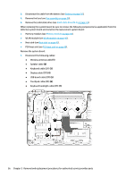
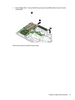
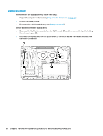
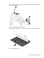
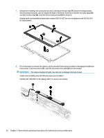
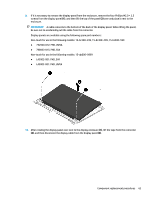
3. Remove the three Phillips M2.5 × 5.0 screws from the left and right hinge brackets (1), and then rotate the hinge brackets upward (2). 4. Position the computer upside-down on the display. 5. Rotate the display assembly (1), and then separate the display assembly from the base enclosure (2). 6. Position the display panel upright. Component replacement procedures 61
-
 1
1 -
2
-
3
-
4
-
5
-
6
-
7
-
8
-
9
-
10
-
11
-
12
-
13
-
14
-
15
-
16
-
17
-
18
-
19
-
20
-
21
-
22
-
23
-
24
-
25
-
26
-
27
-
28
-
29
-
30
-
31
-
32
-
33
-
34
-
35
-
36
-
37
-
38
-
39
-
40
-
41
-
42
-
43
-
44
-
45
-
46
-
47
-
48
-
49
-
50
-
51
-
52
-
53
-
54
-
55
-
56
-
57
-
58
-
59
-
60
-
61
-
62
-
63
-
 64
64 -
 65
65 -
 66
66 -
 67
67 -
 68
68 -
 69
69 -
 70
70 -
 71
71 -
 72
72 -
 73
73 -
 74
74 -
75
-
76
-
77
-
78
-
79
-
80
-
81
-
82
-
83
-
84
-
85
-
86
-
87
-
88
-
89
-
90
-
91
-
92
-
93
-
94
-
95
-
96
-
97
-
98
 |
 |
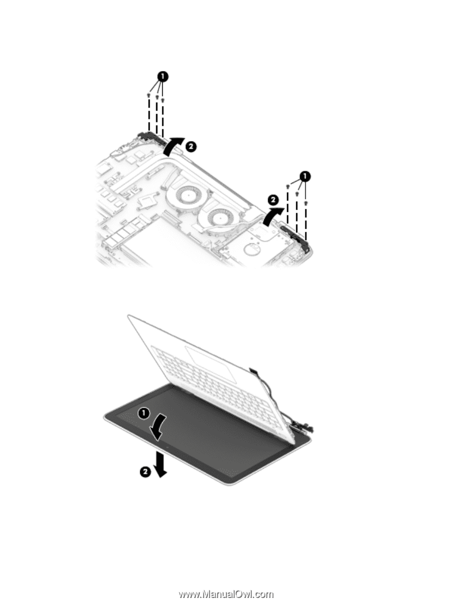
3.
Remove the three Phillips M2.5 × 5.0 screws from the left and right hinge brackets
(1)
, and then rotate
the hinge brackets upward
(2)
.
4.
Position the computer upside-down on the display.
5.
Rotate the display assembly
(1)
, and then separate the display assembly from the base enclosure
(2)
.
6.
Position the display panel upright.
Component replacement procedures
61