HP Pavilion PC 14-dv1000 Maintenance and Service Guide - Page 58
Touchpad cable ZIF, Display cable ZIF
 |
View all HP Pavilion PC 14-dv1000 manuals
Add to My Manuals
Save this manual to your list of manuals |
Page 58 highlights
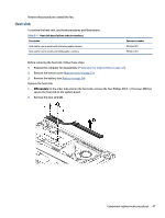
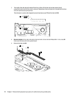
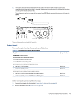
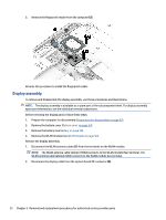
3. Remove the battery (see Battery on page 34). 4. Remove the fan (see Fan on page 45). When you replace the system board, be sure to remove the following components (as applicable) from the defective system board and install them on the replacement system board: ● Memory modules (see Memory modules on page 38). ● WLAN module (see WLAN module on page 36). ● Solid-state drive (see Solid-state drive on page 38). ● Heat sink (see Heat sink on page 47). Remove the system board: 1. Disconnect the following cables from the system board: ● Power connector (DC-in) board cable (1) ● WLAN antennas from the WLAN module (2) ● Display cable (ZIF) (3) ● Keyboard backlight cable (ZIF) (4) (select products only) ● Keyboard cable (ZIF) (5) ● USB board cable (ZIF) (6) ● Touchpad cable (ZIF) (7) ● Speaker cable (8) ● Fingerprint reader cable (ZIF) (9) (select products only) 2. Remove the four Phillips M2.0 × 3.0 screws (1) that secure the system board to the computer. 50 Chapter 5 Removal and replacement procedures for authorized service provider parts
-
 1
1 -
2
-
3
-
4
-
5
-
6
-
7
-
8
-
9
-
10
-
11
-
12
-
13
-
14
-
15
-
16
-
17
-
18
-
19
-
20
-
21
-
22
-
23
-
24
-
25
-
26
-
27
-
28
-
29
-
30
-
31
-
32
-
33
-
34
-
35
-
36
-
37
-
38
-
39
-
40
-
41
-
42
-
43
-
44
-
45
-
46
-
47
-
48
-
49
-
50
-
51
-
52
-
 53
53 -
 54
54 -
 55
55 -
 56
56 -
 57
57 -
 58
58 -
 59
59 -
 60
60 -
 61
61 -
 62
62 -
 63
63 -
64
-
65
-
66
-
67
-
68
-
69
-
70
-
71
-
72
-
73
-
74
-
75
-
76
-
77
-
78
-
79
-
80
-
81
-
82
-
83
-
84
-
85
-
86
-
87
-
88
-
89
 |
 |