HP Pavilion PC 14-dv1000 Maintenance and Service Guide - Page 60
Display assembly, Disconnect the WLAN antenna cables
 |
View all HP Pavilion PC 14-dv1000 manuals
Add to My Manuals
Save this manual to your list of manuals |
Page 60 highlights
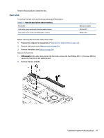
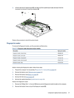
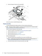
3. Remove the fingerprint reader from the computer (3). Reverse this procedure to install the fingerprint reader. Display assembly To remove and disassemble the display assembly, use these procedures and illustrations. NOTE: The display assembly is available as a spare part at the subcomponent level. For display assembly spare part information, see the individual removal subsections. Before removing the display panel, follow these steps: 1. Prepare the computer for disassembly (Preparation for disassembly on page 32). 2. Remove the bottom cover (Bottom cover on page 32). 3. Remove the battery (see Battery on page 34). 4. Remove the WLAN module (see WLAN module on page 36). Remove the display assembly: 1. Disconnect the WLAN antenna cables (1) from the terminals on the WLAN module. NOTE: The WLAN antenna cable labeled 1/MAIN connects to the WLAN module Main terminal. The WLAN antenna cable labeled 2/AUX connects to the WLAN module Aux terminal. 2. Disconnect the display cable from the system board ZIF connector (2). 52 Chapter 5 Removal and replacement procedures for authorized service provider parts
-
 1
1 -
2
-
3
-
4
-
5
-
6
-
7
-
8
-
9
-
10
-
11
-
12
-
13
-
14
-
15
-
16
-
17
-
18
-
19
-
20
-
21
-
22
-
23
-
24
-
25
-
26
-
27
-
28
-
29
-
30
-
31
-
32
-
33
-
34
-
35
-
36
-
37
-
38
-
39
-
40
-
41
-
42
-
43
-
44
-
45
-
46
-
47
-
48
-
49
-
50
-
51
-
52
-
53
-
54
-
 55
55 -
 56
56 -
 57
57 -
 58
58 -
 59
59 -
 60
60 -
 61
61 -
 62
62 -
 63
63 -
 64
64 -
 65
65 -
66
-
67
-
68
-
69
-
70
-
71
-
72
-
73
-
74
-
75
-
76
-
77
-
78
-
79
-
80
-
81
-
82
-
83
-
84
-
85
-
86
-
87
-
88
-
89
 |
 |
