HP ProBook 6465b HP ProBook 6465b Notebook PC - Maintenance and Service Guide - Page 102
Lift the board up at an angle to gain access to the cables underneath
 |
View all HP ProBook 6465b manuals
Add to My Manuals
Save this manual to your list of manuals |
Page 102 highlights
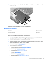
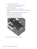
g. Keyboard (see Keyboard on page 67) h. Bottom cover (see Bottom cover from top cover on page 70) i. System board (see System board on page 89) Remove the ExpressCard assembly: 1. Position the computer upside-down with the front toward you. 2. Remove the broadhead Phillips PM2.0×4.0 screw (1) that secures the assembly to the computer. 3. Lift the board up at an angle to gain access to the cables underneath (2). 4. Disconnect the cable from the ExpressCard board (3). 5. Disconnect the cable (4) from the Touchpad board. 6. Lift the assembly straight up and off the computer (5). Reverse this procedure to install the ExpressCard assembly. 94 Chapter 4 Removal and replacement procedures
-
 1
1 -
2
-
3
-
4
-
5
-
6
-
7
-
8
-
9
-
10
-
11
-
12
-
13
-
14
-
15
-
16
-
17
-
18
-
19
-
20
-
21
-
22
-
23
-
24
-
25
-
26
-
27
-
28
-
29
-
30
-
31
-
32
-
33
-
34
-
35
-
36
-
37
-
38
-
39
-
40
-
41
-
42
-
43
-
44
-
45
-
46
-
47
-
48
-
49
-
50
-
51
-
52
-
53
-
54
-
55
-
56
-
57
-
58
-
59
-
60
-
61
-
62
-
63
-
64
-
65
-
66
-
67
-
68
-
69
-
70
-
71
-
72
-
73
-
74
-
75
-
76
-
77
-
78
-
79
-
80
-
81
-
82
-
83
-
84
-
85
-
86
-
87
-
88
-
89
-
90
-
91
-
92
-
93
-
94
-
95
-
96
-
 97
97 -
 98
98 -
 99
99 -
 100
100 -
 101
101 -
 102
102 -
 103
103 -
 104
104 -
 105
105 -
 106
106 -
 107
107 -
108
-
109
-
110
-
111
-
112
-
113
-
114
-
115
-
116
-
117
-
118
-
119
-
120
-
121
-
122
-
123
-
124
-
125
-
126
-
127
-
128
-
129
-
130
-
131
-
132
-
133
-
134
-
135
 |
 |

g.
Keyboard (see
Keyboard
on page
67
)
h.
Bottom cover (see
Bottom cover from top cover
on page
70
)
i.
System board (see
System board
on page
89
)
Remove the ExpressCard assembly:
1.
Position the computer upside-down with the front toward you.
2.
Remove the broadhead Phillips PM2.0×4.0 screw
(1)
that secures the assembly to the
computer.
3.
Lift the board up at an angle to gain access to the cables underneath
(2)
.
4.
Disconnect the cable from the ExpressCard board
(3)
.
5.
Disconnect the cable
(4)
from the Touchpad board.
6.
Lift the assembly straight up and off the computer
(5)
.
Reverse this procedure to install the ExpressCard assembly.
94
Chapter 4
Removal and replacement procedures