HP ProBook 6465b HP ProBook 6465b Notebook PC - Maintenance and Service Guide - Page 98
When replacing the system board, be sure that the following components are removed from
 |
View all HP ProBook 6465b manuals
Add to My Manuals
Save this manual to your list of manuals |
Page 98 highlights
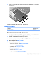
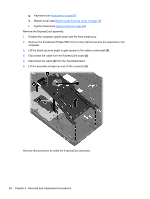
d. Fan (see Fan on page 63) e. Heat sink (see Heat sink on page 64) f. Keyboard (see Keyboard on page 67) g. Bottom cover (see Bottom cover from top cover on page 70) When replacing the system board, be sure that the following components are removed from the defective system board and installed on the replacement system board: ● SIM (see SIM on page 42) ● Memory module (see Memory modules on page 55) ● WLAN module (see WLAN module on page 59) ● WWAN module (see WWAN module on page 57) ● Modem module (see Modem module on page 62) ● Processor (see Processor on page 66) Remove the system board: 1. Position the computer right-side up, with the front toward you. 2. Disconnect the following cables from the system board (as necessary): ● (1): Antenna cables from the rubber clamp ● (2): Lid sensor board cable ● (3): Display cable ● (4): Webcam cable ● (5): Fingerprint reader cable ● (6): RTC battery cable 90 Chapter 4 Removal and replacement procedures
-
 1
1 -
2
-
3
-
4
-
5
-
6
-
7
-
8
-
9
-
10
-
11
-
12
-
13
-
14
-
15
-
16
-
17
-
18
-
19
-
20
-
21
-
22
-
23
-
24
-
25
-
26
-
27
-
28
-
29
-
30
-
31
-
32
-
33
-
34
-
35
-
36
-
37
-
38
-
39
-
40
-
41
-
42
-
43
-
44
-
45
-
46
-
47
-
48
-
49
-
50
-
51
-
52
-
53
-
54
-
55
-
56
-
57
-
58
-
59
-
60
-
61
-
62
-
63
-
64
-
65
-
66
-
67
-
68
-
69
-
70
-
71
-
72
-
73
-
74
-
75
-
76
-
77
-
78
-
79
-
80
-
81
-
82
-
83
-
84
-
85
-
86
-
87
-
88
-
89
-
90
-
91
-
92
-
 93
93 -
 94
94 -
 95
95 -
 96
96 -
 97
97 -
 98
98 -
 99
99 -
 100
100 -
 101
101 -
 102
102 -
 103
103 -
104
-
105
-
106
-
107
-
108
-
109
-
110
-
111
-
112
-
113
-
114
-
115
-
116
-
117
-
118
-
119
-
120
-
121
-
122
-
123
-
124
-
125
-
126
-
127
-
128
-
129
-
130
-
131
-
132
-
133
-
134
-
135
 |
 |
