HP ProDesk 600 G4 Micro Maintenance and Service Guide - Page 54
Fan-sink, Loosen the four slotted Torx-15 captive screws
 |
View all HP ProDesk 600 G4 Micro manuals
Add to My Manuals
Save this manual to your list of manuals |
Page 54 highlights
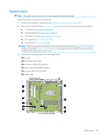
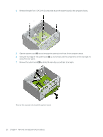
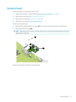
Fan-sink NOTE: The fan-sink spare park kit includes replacement thermal material. Follow these steps to remove the fan-sink: 1. Prepare the computer for disassembly (see Preparation for disassembly on page 30). 2. Remove the access panel (see Access panel on page 31). 3. Remove the front bezel (see Front bezel on page 34). 4. Remove the drive cage (see Drive cage on page 38). Remove the fan-sink: 1. Remove the drive power cables and data cables from the retention clips (1) built into the fan-sink. 2. Disconnect the fan-sink cable (1) from the system board. 3. Loosen the four slotted Torx-15 captive screws (2) that secure the fan-sink to the computer chassis. NOTE: Due to the adhesive nature of the thermal material located between the fan-sink and the processor, it may be necessary to move the fan-sink from side to side when removing the it. 4. Remove the fan-sink (3). Reverse this procedure to install the fan-sink. 46 Chapter 4 Removal and replacement procedures
-
 1
1 -
2
-
3
-
4
-
5
-
6
-
7
-
8
-
9
-
10
-
11
-
12
-
13
-
14
-
15
-
16
-
17
-
18
-
19
-
20
-
21
-
22
-
23
-
24
-
25
-
26
-
27
-
28
-
29
-
30
-
31
-
32
-
33
-
34
-
35
-
36
-
37
-
38
-
39
-
40
-
41
-
42
-
43
-
44
-
45
-
46
-
47
-
48
-
 49
49 -
 50
50 -
 51
51 -
 52
52 -
 53
53 -
 54
54 -
 55
55 -
 56
56 -
 57
57 -
 58
58 -
 59
59 -
60
-
61
-
62
-
63
-
64
-
65
-
66
-
67
-
68
-
69
-
70
-
71
-
72
-
73
-
74
-
75
-
76
-
77
-
78
-
79
-
80
-
81
-
82
-
83
-
84
-
85
-
86
-
87
-
88
-
89
-
90
-
91
-
92
-
93
-
94
-
95
-
96
-
97
-
98
-
99
-
100
-
101
-
102
-
103
-
104
-
105
-
106
-
107
-
108
-
109
-
110
-
111
-
112
-
113
-
114
-
115
-
116
-
117
-
118
-
119
-
120
-
121
-
122
-
123
-
124
-
125
-
126
-
127
-
128
-
129
-
130
 |
 |
