HP ProDesk 600 G4 Micro Maintenance and Service Guide - Page 59
Connector board
 |
View all HP ProDesk 600 G4 Micro manuals
Add to My Manuals
Save this manual to your list of manuals |
Page 59 highlights
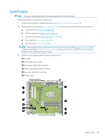
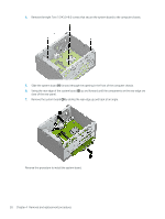
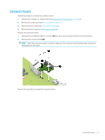
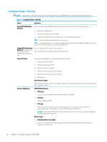
Connector board Follow these steps to remove the connector board: 1. Prepare the computer for disassembly (see Preparation for disassembly on page 30). 2. Remove the access panel (see Access panel on page 31). 3. Remove the front bezel (see Front bezel on page 34). 4. Remove the drive cage (see Drive cage on page 38). Remove the connector board: 1. Remove the two Phillips PM2.0×3.5 screws (1) that secure the connector board to the system board. 2. Remove the connector board (2). NOTE: When the connector board is removed, make sure the connector board bracket does not become separated from the board. Reverse this procedure to install the connector board. Connector board 51
-
 1
1 -
2
-
3
-
4
-
5
-
6
-
7
-
8
-
9
-
10
-
11
-
12
-
13
-
14
-
15
-
16
-
17
-
18
-
19
-
20
-
21
-
22
-
23
-
24
-
25
-
26
-
27
-
28
-
29
-
30
-
31
-
32
-
33
-
34
-
35
-
36
-
37
-
38
-
39
-
40
-
41
-
42
-
43
-
44
-
45
-
46
-
47
-
48
-
49
-
50
-
51
-
52
-
53
-
 54
54 -
 55
55 -
 56
56 -
 57
57 -
 58
58 -
 59
59 -
 60
60 -
 61
61 -
 62
62 -
 63
63 -
 64
64 -
65
-
66
-
67
-
68
-
69
-
70
-
71
-
72
-
73
-
74
-
75
-
76
-
77
-
78
-
79
-
80
-
81
-
82
-
83
-
84
-
85
-
86
-
87
-
88
-
89
-
90
-
91
-
92
-
93
-
94
-
95
-
96
-
97
-
98
-
99
-
100
-
101
-
102
-
103
-
104
-
105
-
106
-
107
-
108
-
109
-
110
-
111
-
112
-
113
-
114
-
115
-
116
-
117
-
118
-
119
-
120
-
121
-
122
-
123
-
124
-
125
-
126
-
127
-
128
-
129
-
130
 |
 |

Connector board
Follow these steps to remove the connector board:
1.
Prepare the computer for disassembly (see
Preparation for disassembly
on page
30
).
2.
Remove the access panel (see
Access panel
on page
31
).
3.
Remove the front bezel (see
Front bezel
on page
34
).
4.
Remove the drive cage (see
Drive cage
on page
38
).
Remove the connector board:
1.
Remove the two Phillips PM2.0×3.5 screws
(1)
that secure the connector board to the system board.
2.
Remove the connector board
(2)
.
NOTE:
When the connector board is removed, make sure the connector board bracket does not become
separated from the board.
Reverse this procedure to install the connector board.
Connector board
51