HP ProDesk 600 G4 Micro Maintenance and Service Guide - Page 57
System board, are removed from the defective system board
 |
View all HP ProDesk 600 G4 Micro manuals
Add to My Manuals
Save this manual to your list of manuals |
Page 57 highlights
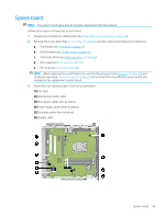
System board NOTE: The system board spare park kit includes replacement thermal material. Follow these steps to remove the system board: 1. Prepare the computer for disassembly (see Preparation for disassembly on page 30). 2. Remove the access panel (see Access panel on page 31), and then remove the following components: a. Front bezel (see Front bezel on page 34) b. WLAN module (see WLAN module on page 41) c. Solid-state drive (see Solid-state drive on page 42) d. Drive cage (see Drive cage on page 38) e. Fan-sink (see Fan-sink on page 46) NOTE: When replacing the system board, be sure that the processor (see Processor on page 47) and connector board (see Connector board on page 51) are removed from the defective system board and installed on the replacement system board. 3. Disconnect the following cables from the system board: (1) Fan cable (2) Hood sensor switch cable (3) Drive power cables (two locations) (4) Power supply cables (three locations) (5) Drive data cables (four locations) (6) Speaker cable System board 49
-
 1
1 -
2
-
3
-
4
-
5
-
6
-
7
-
8
-
9
-
10
-
11
-
12
-
13
-
14
-
15
-
16
-
17
-
18
-
19
-
20
-
21
-
22
-
23
-
24
-
25
-
26
-
27
-
28
-
29
-
30
-
31
-
32
-
33
-
34
-
35
-
36
-
37
-
38
-
39
-
40
-
41
-
42
-
43
-
44
-
45
-
46
-
47
-
48
-
49
-
50
-
51
-
 52
52 -
 53
53 -
 54
54 -
 55
55 -
 56
56 -
 57
57 -
 58
58 -
 59
59 -
 60
60 -
 61
61 -
 62
62 -
63
-
64
-
65
-
66
-
67
-
68
-
69
-
70
-
71
-
72
-
73
-
74
-
75
-
76
-
77
-
78
-
79
-
80
-
81
-
82
-
83
-
84
-
85
-
86
-
87
-
88
-
89
-
90
-
91
-
92
-
93
-
94
-
95
-
96
-
97
-
98
-
99
-
100
-
101
-
102
-
103
-
104
-
105
-
106
-
107
-
108
-
109
-
110
-
111
-
112
-
113
-
114
-
115
-
116
-
117
-
118
-
119
-
120
-
121
-
122
-
123
-
124
-
125
-
126
-
127
-
128
-
129
-
130
 |
 |
