HP ProDesk 600 G4 Micro Maintenance and Service Guide - Page 55
Processor, Drive cage see
 |
View all HP ProDesk 600 G4 Micro manuals
Add to My Manuals
Save this manual to your list of manuals |
Page 55 highlights
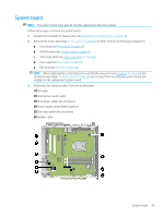
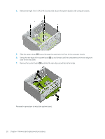
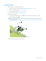
Processor NOTE: The processor spare park kit includes replacement thermal material. Follow these steps to remove the fan-sink: 1. Prepare the computer for disassembly (see Preparation for disassembly on page 30), and then remove the following components: 2. Remove the access panel (see Access panel on page 31), and then remove the following components: a. Front bezel (see Front bezel on page 34) b. Drive cage (see Drive cage on page 38) c. Fan-sink (see Fan-sink on page 46) Remove the processor: 1. Depress the processor release lever (1), and then slide the lever to the right until it clears the locking clip. 2. Swing the processor release lever (2) up and back as far as it will go. 3. Swing the processor retention bracket (3) up and back as far as it will go. Processor 47
-
 1
1 -
2
-
3
-
4
-
5
-
6
-
7
-
8
-
9
-
10
-
11
-
12
-
13
-
14
-
15
-
16
-
17
-
18
-
19
-
20
-
21
-
22
-
23
-
24
-
25
-
26
-
27
-
28
-
29
-
30
-
31
-
32
-
33
-
34
-
35
-
36
-
37
-
38
-
39
-
40
-
41
-
42
-
43
-
44
-
45
-
46
-
47
-
48
-
49
-
 50
50 -
 51
51 -
 52
52 -
 53
53 -
 54
54 -
 55
55 -
 56
56 -
 57
57 -
 58
58 -
 59
59 -
 60
60 -
61
-
62
-
63
-
64
-
65
-
66
-
67
-
68
-
69
-
70
-
71
-
72
-
73
-
74
-
75
-
76
-
77
-
78
-
79
-
80
-
81
-
82
-
83
-
84
-
85
-
86
-
87
-
88
-
89
-
90
-
91
-
92
-
93
-
94
-
95
-
96
-
97
-
98
-
99
-
100
-
101
-
102
-
103
-
104
-
105
-
106
-
107
-
108
-
109
-
110
-
111
-
112
-
113
-
114
-
115
-
116
-
117
-
118
-
119
-
120
-
121
-
122
-
123
-
124
-
125
-
126
-
127
-
128
-
129
-
130
 |
 |
