HP ProLiant DL980 DL980 G7 User Installation Guide - Page 8
Front panel LEDs
 |
View all HP ProLiant DL980 manuals
Add to My Manuals
Save this manual to your list of manuals |
Page 8 highlights
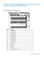
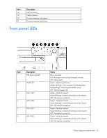
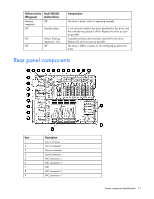
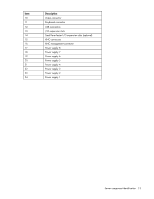
Item 18 19 20 21 Description USB connectors Video connector Processor memory tray (upper) Processor memory tray (lower) Front panel LEDs Item Description 1 UID button and LED 2 Health LED 3 NIC 1 LED 4 NIC 2 LED 5 NIC 3 LED 6 NIC 4 LED Status Blue-Activated Blue (flashing)-Server being managed remotely Off-Deactivated Green-Normal (system on) Amber (flashing)-Internal system health degraded Red (flashing)-Internal system health critical Off-Normal (system off) Green-Linked to network Green (flashing)-Linked with activity on the network Off-No network connection Green-Linked to network Green (flashing)-Linked with activity on the network Off-No network connection Green-Linked to network Green (flashing)-Linked with activity on the network Off-No network connection Green-Linked to network Green (flashing)-Linked with activity on the network Off-No network connection Server component identification 8
-
 1
1 -
2
-
 3
3 -
 4
4 -
 5
5 -
 6
6 -
 7
7 -
 8
8 -
 9
9 -
 10
10 -
 11
11 -
 12
12 -
 13
13 -
14
-
15
-
16
-
17
-
18
-
19
-
20
-
21
-
22
-
23
-
24
-
25
-
26
-
27
-
28
-
29
-
30
-
31
-
32
-
33
-
34
-
35
-
36
-
37
-
38
-
39
-
40
-
41
-
42
-
43
-
44
-
45
-
46
-
47
-
48
-
49
-
50
-
51
-
52
-
53
-
54
-
55
-
56
-
57
-
58
-
59
-
60
-
61
-
62
-
63
-
64
-
65
-
66
-
67
-
68
-
69
-
70
-
71
-
72
-
73
-
74
-
75
-
76
-
77
-
78
-
79
-
80
-
81
-
82
-
83
-
84
-
85
-
86
-
87
-
88
-
89
-
90
-
91
-
92
-
93
-
94
-
95
-
96
-
97
-
98
-
99
-
100
-
101
-
102
-
103
-
104
-
105
-
106
-
107
-
108
-
109
-
110
-
111
-
112
-
113
-
114
-
115
-
116
-
117
-
118
-
119
-
120
-
121
-
122
-
123
-
124
-
125
-
126
-
127
-
128
 |
 |
